
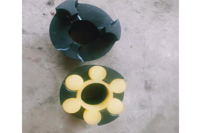
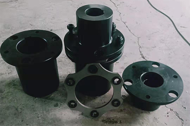
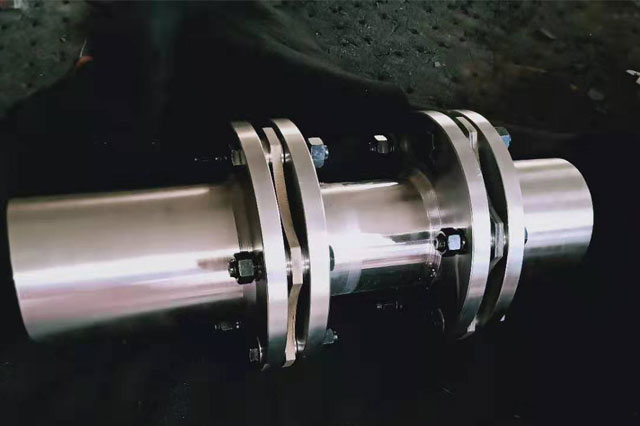
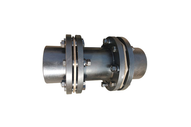
Installation instructions for JMIJ-type diaphragm coupling with intermediate shaft
1. Before installation, first check whether the prime mover and the working machine are concentric, whether there are wrapping paper and scratches on the surfaces of the two shafts, whether there are debris in the inner holes of the two half couplings of the coupling, and whether there is any edge of the inner hole. If there are bruises, the shaft and half coupling should be cleaned up, and the bruises should be treated with a fine file.Then check whether the inner hole diameter and length of the two half couplings are consistent with the diameter and shaft elongation of the prime mover and working machine.In general selection, it is better to make the length of the prime mover and the working machine end half-coupling less than its shaft elongation 10-30mm.
2. In order to facilitate the installation, it is best to put the two half couplings in the 120-150 incubator or oil tank for preheating, so that the inner hole size increases and it is easy to install.After installation, ensure that the shaft head cannot protrude from the end face of the half coupling, and it is better to be flush.Detect the distance between the two halves of the coupling: take the average of the readings of 3-4 points measured along the two inner sides of the flange of the half coupling, and the sum of the measured dimensions of the extension and the two diaphragm sets, two The error is controlled within the range of 0-0.4mm.
3. 找正:用百分表检测两半联轴节法兰盘端面和外圆跳动,当法兰盘外圆小于250mm时跳动值应不大于0.05mm;当法兰盘外圆大于250mm时,跳动值应不大于0.08.
model | Nominal torque | Momentary maximum torque Tmax | Permissible speed | Diameter of shaft hole d(H 7) | Shaft hole shaft hole shaft hole shaft hole | D | t | L2 | Moment of inertia I/kg.m 2 ≈ | Mass m/kg ≈ | |||
Y type | J, J1, Z, Z1 type | L recommended | |||||||||||
L | L | L1 | |||||||||||
JMIJ1 | 25 | 80 | 6000 | 14 | 32 | - | J1 type is 27 Z1 type is 20 | 35 | 90 | 8.8 | 100 | 0.0013 | 1.8 |
16, 18, 19 | 42 | 30 | |||||||||||
20, 22 |
| 38 | |||||||||||
JMIJ2 | 63 | 180 | 5000 | 18, 19 | 42 | - | 30 | 45 | 100 | 9.5 | 100 | 0.002 | 2.4 |
20, 22, 24 | 52 | 38 | |||||||||||
25 | 62 | 44 | |||||||||||
JMIJ3 | 100 | 315 | 5000 | 20, 22, 24 | 52 | - | 38 | 50 | 120 | 11 | 120 | 0.0047 | 4.1 |
25, 28 | 62 | 44 | |||||||||||
30 | 82 | 60 | |||||||||||
JMIJ4 | 160 | 500 | 4500 | 24 | 52 | - | 38 | 55 | 130 | 12.5 | 120 | 0.0069 | 5.4 |
25, 28 | 62 | 44 | |||||||||||
30, 32, 35 | 82 | 60 | |||||||||||
JMIJ5 | 250 | 710 | 4000 | 28 | 62 | - | 44 | 60 | 150 | 14 | 140 | 0.0153 | 8.8 |
30-32-35 | 82 | 60 | |||||||||||
40 | 112 | 84 | |||||||||||
JMIJ6 | 400 | 1120 | 3600 | 32, 35, 38 | 82 | 82 | 60 | 65 | 170 | 15.5 | 140 | 0.0281 | 13.4 |
40, 42, 45, 48, 50 | 112 | - | 84 | ||||||||||
JMIJ7 | 630 | 1800 | 3000 | 40, 42 | 112 | 112 | 84 | 70 | 210 | 19 | 150 | 0.076 | 22.3 |
45, 48, 50, 55, 56 |
| ||||||||||||
60 | 142 | 107 | |||||||||||
JMIJ8 | 1000 | 2500 | 2800 | 45, 48 | 112 | 112 | 84 | 80 | 240 | 22.5 | 180 | 0.1602 | 36 |
50, 55, 56 |
| ||||||||||||
60-63-65 | 142 | 107 | |||||||||||
JMIJ9 | 1600 | 4000 | 2500 | 55, 56 | 112 | 112 | 84 | 85 | 260 | 24 | 220 | 0.2509 | 48 |
60, 63, 65, 70, 71, 75 | 142 |
| 107 | ||||||||||
80 | 172 | 132 | |||||||||||
JMIJ10 | 2500 | 6300 | 2000 | 63, 65, 70, 71, 75 | 142 | 142 | 107 | 90 | 280 | 17 | 250 | 0.5195 | 85 |
80-85-90 | 172 | - | 132 | ||||||||||
JMIJ11 | 4000 | 9000 | 1800 | 75 | 142 | 142 | 107 | 95 | 300 | 19.5 | 290 | 0.8223 | 112 |
80-85-90 | 172 | 172 | 132 | ||||||||||
100, 110 | 212 | - | 167 | ||||||||||
JMIJ12 | 6300 | 12500 | 1600 | 90, 95 | 172 |
| 132 | 120 | 340 | 23 | 300 | 1.4109 | 152 |
|
|
| |||||||||||
