

XNUMX. Product overview
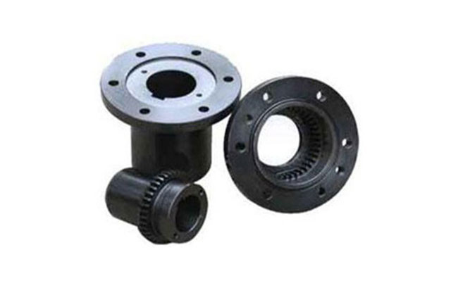
The slider of the slider coupling has a circular ring shape and is made of steel or wear-resistant alloy. The intermediate slider is used to slide in the corresponding radial grooves on the end faces of the half couplings on both sides to complete the two half couplings. The connection is mainly suitable for the transmission with low speed and large transmission torque.
XNUMX. Product structure
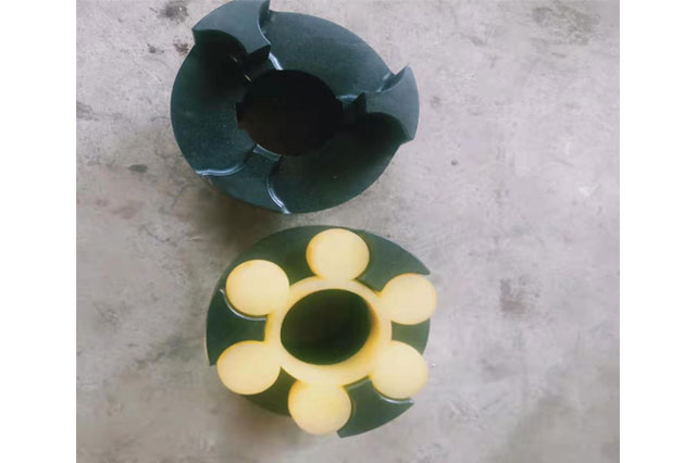
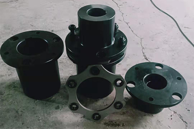
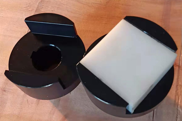
The slider coupling is composed of two half couplings with grooves on the end faces and an intermediate disc with convex teeth on both sides. The convex teeth can slide in the grooves to compensate the device and the two shafts during operation. The center slider is usually made of engineering plastics as a torque transmission element, and other materials can be selected under special conditions.
Three, product characteristics
1. The material of the sliding block coupling parts can be made of 45 steel, and the work surface needs to stop heat treatment to improve its hardness;
2. A slight pressure is used to stop the anastomosis between the center slider and the shaft sleeve, which can make the coupling run with zero clearance during the operation of the equipment;
3. The half-coupling and the intermediate disc form a moving pair, which cannot rotate relative to each other. Therefore, the angular velocity of the driving shaft and the driven shaft should be equal, and the working speed should not be greater than the regular value when selecting;
4. The central sliding block is connected to the shaft sleeves on both sides through the clamping slots which are 90° on both sides, so as to achieve the purpose of transmitting torque;
5. Slider couplings are often used in common motors, and individual places can also be used to connect servo motors, and the relative displacement can be corrected by the sliding of the center slider during use.
| model | Nominal torque Tn(Nm) | Allowable speed [n]r/min | Diameter of shaft hole | Length of shaft hole | D | D1 | B1 | B2 | l | Moment of inertia Kg.m2 | Mass kg | |
| d1 d2 | Y | J1 | ||||||||||
| L | ||||||||||||
| mm | ||||||||||||
WH1 | 16 | 10000 | 10,11 12,14 | 25-32 | 22-27 | 40 | 30 | 52 | 13 | 5 | 0.0007 | 0.6 |
| 32-42 | 27-30 | |||||||||||
| WH2 | 31.5 | 8200 | 12,12,16,(17),18 | 50 | 32 | 56 | 18 | 5 | 0.0038 | 1.5 | ||
WH3 | 63 | 7000 | 16,(17),18,20,22 | 42-52 | 30-38 | 70 | 40 | 60 | 18 | 5 | 0.0063 | 1.8 |
52-62 | 38-44 | |||||||||||
| WH4 | 160 | 5700 | 20,22,24,25,28 | 80 | 50 | 64 | 18 | 8 | 0.013 | 2.5 | ||
WH5 | 280 | 4700 | 25,28,30,32,35 | 62-82 | 44-60 | 100 | 70 | 75 | 23 | 10 | 0.045 | 5.8 |
82-112 | 60-84 | |||||||||||
| WH6 | 500 | 3800 | 30,32,35,38,40,42,45 | 120 | 80 | 90 | 33 | 15 | 0.12 | 9.5 | ||
WH7 | 900 | 3200 | 40,42,45,48,50,55 | 112 | 84 | 150 | 100 | 120 | 38 | 25 | 0.43 | 25 |
112-142 | 84-107 | |||||||||||
| WH8 | 1800 | 2400 | 50,55,60,63,65,70 | 190 | 120 | 150 | 48 | 25 | 1.98 | 55 | ||
WH9 | 3550 | 1800 | 65,70,75,80,85 | 172-212 | 132-167 | 330 | 190 | 180 | 58 | 40 | 4.9 | 85 |
172-212 | 132-167 | |||||||||||
| WH10 | 5000 | 1500 | 80,85,90,95,100 | 330 | 190 | 180 | 58 | 40 | 7.5 | 120 | ||
