
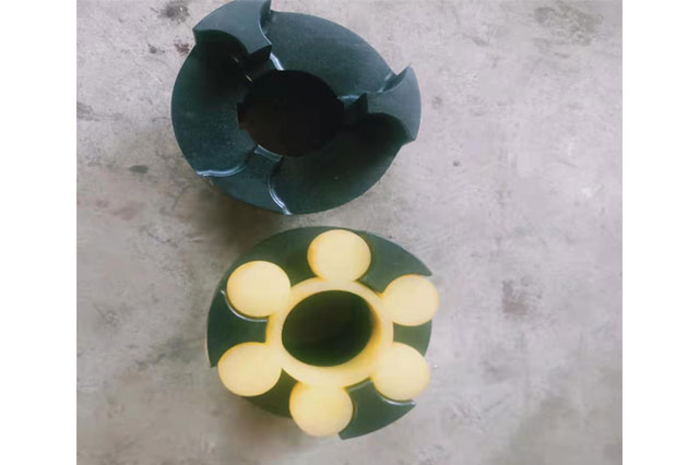
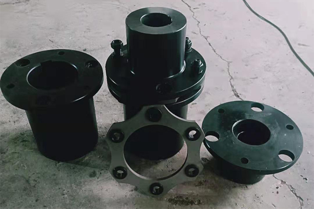
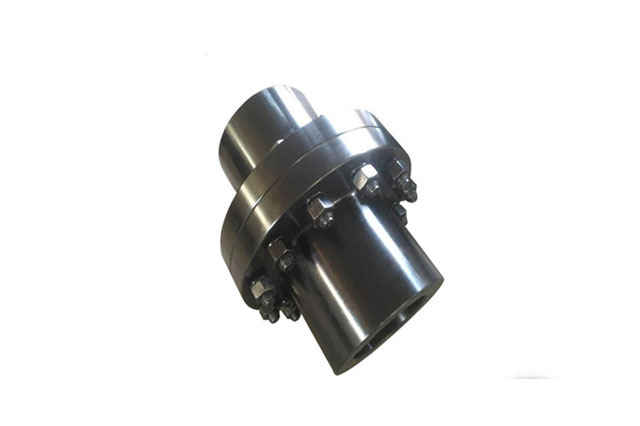
Flange coupling is a rigid coupling. It connects two flanged half couplings with ordinary flat keys to the two shafts, and then connects the two half couplings with bolts to transmit motion. And torque.There are two main structural forms of this coupling:
1. Rely on reamed holes and bolts to achieve two-axis alignment and rely on bolt rods to bear extrusion and shear to transmit torque;
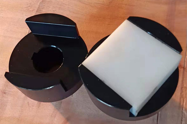
2. It is centered by matching the convex shoulder on one half coupling with the groove on the other half coupling.The bolts connecting the two half-couplings can be ordinary bolts of grade A and B, and the torque is transmitted by the frictional moment of the joint surface of the two half-couplings.
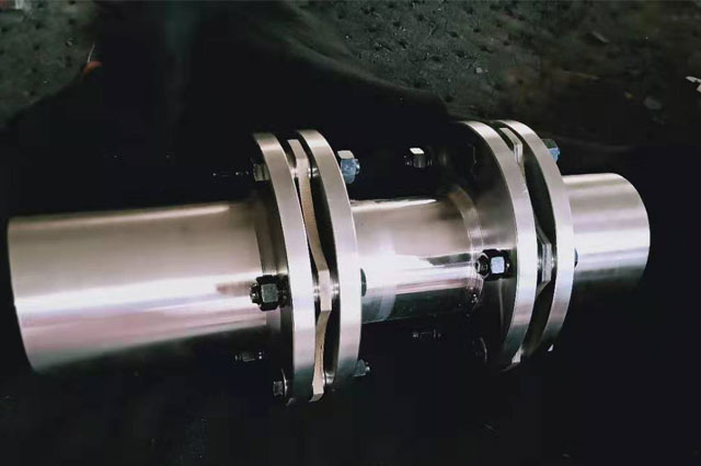
The material of the flange coupling can be gray cast iron or carbon steel, and cast steel or forged steel should be used for heavy loads or when the peripheral speed is greater than 30 m/s.Flange couplings have high requirements for the neutrality of the two shafts. When the two shafts have relative displacement, they will cause additional loads in the machine parts and worsen the working conditions. This is its main disadvantage.However, due to its simple structure, low cost, and large torque transmission, it is often used when the speed is low, there is no impact, the shaft is rigid, and the neutrality is good.
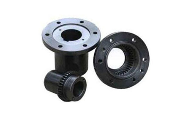
According to the national standard GB/T5843-2003, it can be divided into three types: GY flange coupling, GYS flange coupling with centering tenon, and GYH flange coupling with centering ring.

| model | Nominal torque Tn Nm | Allowable torque (n) r/min | Diameter of shaft hole d | Shaft hole length L | Size mm | Moment of inertia kg.m2 | Maximum weight kg | ||||
| D | D1 | b | b1 | S | |||||||
| GY1 | 25 | 12000 | 12-19 | 27-42 | 80 | 30 | 26 | 42 | 6 | 0.0008 | 1.16 |
| GYS1 | |||||||||||
| GYH1 | |||||||||||
| GY2 | 63 | 10000 | 16-25 | 30-62 | 90 | 40 | 28 | 44 | 6 | 0.0015 | 1.72 |
| GYS2 | |||||||||||
| GYH2 | |||||||||||
| GY3 | 112 | 9500 | 20-28 | 38-62 | 100 | 45 | 30 | 46 | 6 | 0.0025 | 2.38 |
| GYS3 | |||||||||||
| GYH3 | |||||||||||
| GY4 | 224 | 9000 | 25-35 | 44-82 | 105 | 55 | 32 | 48 | 6 | 0.003 | 3.15 |
| GYS4 | |||||||||||
| GYH4 | |||||||||||
| GY5 | 400 | 8000 | 30-42 | 60-112 | 120 | 68 | 36 | 52 | 8 | 0.007 | 5.43 |
| GYS5 | |||||||||||
| GYH5 | |||||||||||
| GY6 | 900 | 6800 | 38-50 | 60-112 | 140 | 80 | 40 | 56 | 8 | 0.015 | 7.59 |
| GYS6 | |||||||||||
| GYH6 | |||||||||||
| GY7 | 1600 | 6000 | 48-63 | 84-142 | 160 | 100 | 40 | 56 | 8 | 0.031 | 13.1 |
| GYS7 | |||||||||||
| GYH7 | |||||||||||
| GY8 | 3150 | 4800 | 60-80 | 107-172 | 200 | 130 | 50 | 68 | 10 | 0.103 | 27.5 |
| GYS8 | |||||||||||
| GYH8 | |||||||||||
| GY9 | 6300 | 3600 | 75-100 | 107-212 | 260 | 160 | 66 | 84 | 10 | 0.319 | 47.8 |
| GYS9 | |||||||||||
| GYH9 | |||||||||||
| GY10 | 10000 | 3200 | 90-125 | 132-212 | 300 | 200 | 72 | 90 | 10 | 0.720 | 82.0 |
| GYS10 | |||||||||||
| GYH10 | |||||||||||
| GY11 | 25000 | 2500 | 120-160 | 167-302 | 380 | 260 | 80 | 98 | 10 | 2.278 | 162.2 |
| GYS11 | |||||||||||
| GYH11 | |||||||||||
| GY12 | 50000 | 2000 | 150-200 | 242-352 | 460 | 320 | 92 | 112 | 12 | 5.923 | 285.6 |
| GYS12 | |||||||||||
| GYH12 | |||||||||||
| GY13 | 100000 | 1600 | 190-250 | 282-410 | 590 | 400 | 110 | 130 | 12 | 19.978 | 611.9 |
| GYS13 | |||||||||||
| GYH13 | |||||||||||
