
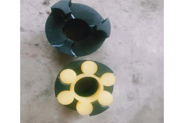
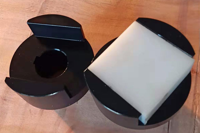
The Oldham slider coupling is also known as the metal slider coupling. The slider has a circular ring shape and is made of steel or wear-resistant alloy. It is suitable for transmissions with low speed and large transmission torque.The Oldham coupling is composed of two half couplings with grooves on the end faces and an intermediate disc with protruding teeth on both sides.Because the convex teeth can slide in the groove, the relative displacement between the two shafts during installation and operation can be compensated.The material of the coupling parts can be 45 steel, and the working surface needs to be heat treated to increase its hardness; Q275 steel can also be used when the requirements are lower, without heat treatment.In order to reduce friction and wear, oil should be injected from the oil hole of the middle plate for lubrication during use.Because the half-coupling and the intermediate disc form a moving pair and cannot rotate relative to each other, the angular velocity of the driving shaft and the driven shaft should be equal.However, when working with relative displacement between the two shafts, the middle disk will generate a large centrifugal force, which will increase the dynamic load and wear.Therefore, pay attention to the working speed not greater than the specified value when selecting.This kind of coupling is generally used for speed n<250r/min, the rigidity of the shaft is relatively large, and there is no severe impact.

model | Nominal torqueTn N·m | Allowable speed [n] r / min | Diameter of shaft holed | D | D1 | L | H | S | Moment of inertia kg·m2 | weight kg |
SL70 | 120 | 250 | 15-18 | 70 | 32 | 42 | 14 | 0.5 | 0.002 | 1.5 |
SL90 | 250 | 250 | 20-30 | 90 | 45 | 52 | 14 | 0.008 | 2.6 | |
SL100 | 500 | 250 | 36-40 | 110 | 60 | 70 | 19 | 0.026 | 5.5 | |
SL130 | 800 | 250 | 45-50 | 130 | 80 | 90 | 19 | 0.07 | 10 | |
SL150 | 1250 | 250 | 55-60 | 150 | 95 | 112 | 19 | 0.14 | 15.5 | |
SL170 | 2000 | 250 | 65-70 | 170 | 105 | 125 | 24 | 0.25 | 22.4 | |
SL190 | 3200 | 250 | 75-80 | 190 | 110 | 140 | 29 | 0.5 | 31.5 | |
SL210 | 5000 | 250 | 85-90 | 210 | 130 | 160 | 33 | 1 | 0.9 | 45 |
SL240 | 8000 | 250 | 95-100 | 240 | 140 | 180 | 33 | 1.6 | 59.5 | |
SL260 | 9000 | 250 | 100-110 | 260 | 160 | 190 | 33 | 2 | 76 | |
SL280 | 10000 | 100 | 110-120 | 280 | 170 | 200 | 33 | 3 | 94.3 | |
SL300 | 13000 | 100 | 120-130 | 300 | 180 | 210 | 43 | 4.3 | 111 | |
SL320 | 16000 | 100 | 130-140 | 320 | 190 | 220 | 43 | 5.7 | 129 | |
SL340 | 20000 | 100 | 150 | 340 | 210 | 250 | 48 | 8.4 | 162 | |
SL360 | 32500 | 100 | 160 | 360 | 240 | 280 | 48 | 19.2 | 258 | |
SL400 | 38700 | 80 | 170 | 400 | 260 | 300 | 48 | 26.1 | 3.5 | |
SL460 | 63000 | 70 | 200 | 460 | 300 | 350 | 58 | 62.9 | 560 |
