Category Archives: helical coupling

China Sorze Coupling Aluminum/Brass Fitting for Fire Hose coupling efficiency

Product Description

ZHangZhoug CZPT Hearth Gear Co., Ltd, which is a non-public organization and set up in 1993. The manufacturing facility is situated in Pingshui city, HangZhou Metropolis, ZHangZhoug province. It is only 5 kilometers from the downtwon. It addresses an spot of 30000 squarmeters. We possess a total established of manufacturing and testing gear. We focus in all kinds of fire hose with the brand name CZPT and once-a-year output amounts to 24 million mneters. 

Our business constantly insisits on the theory of substantial good quality goods and the effort of all employees. Our company has received ISO9001, MED, EN14540, CNBOP, SII, EN694, Ghost certification. 

We will offer you the items which are equally superb in top quality and affordable in value. If you want to discover a lot more about our organization and prodcuts, remember to let us know. We will be happy to offer you you the data that you require.


US $5
/ Set
|
1,000 Sets

(Min. Order)

###

Standard: GB
Material: Aluminum or Brass
Connection: Female or Male
Surface Treatment: Without Treatment
Head Type: Sorze
Size: 1-4inch

###

Samples:
US$ 5/Set
1 Set(Min.Order)

|
Request Sample

###

Customization:
US $5
/ Set
|
1,000 Sets

(Min. Order)

###

Standard: GB
Material: Aluminum or Brass
Connection: Female or Male
Surface Treatment: Without Treatment
Head Type: Sorze
Size: 1-4inch

###

Samples:
US$ 5/Set
1 Set(Min.Order)

|
Request Sample

###

Customization:

Functions and Modifications of Couplings

A coupling is a mechanical device that connects two shafts and transmits power. Its main purpose is to join two rotating pieces of equipment together, and it can also be used to allow some end movement or misalignment. There are many different types of couplings, each serving a specific purpose.

Functions

Functions of coupling are useful tools to study the dynamical interaction of systems. These functions have a wide range of applications, ranging from electrochemical processes to climate processes. The research being conducted on these functions is highly interdisciplinary, and experts from different fields are contributing to this issue. As such, this issue will be of interest to scientists and engineers in many fields, including electrical engineering, physics, and mathematics.
To ensure the proper coupling of data, coupling software must perform many essential functions. These include time interpolation and timing, and data exchange between the appropriate nodes. It should also guarantee that the time step of each model is divisible by the data exchange interval. This will ensure that the data exchange occurs at the proper times.
In addition to transferring power, couplings are also used in machinery. In general, couplings are used to join two rotating pieces. However, they can also have other functions, including compensating for misalignment, dampening axial motion, and absorbing shock. These functions determine the coupling type required.
The coupling strength can also be varied. For example, the strength of the coupling can change from negative to positive. This can affect the mode splitting width. Additionally, coupling strength is affected by fabrication imperfections. The strength of coupling can be controlled with laser non-thermal oxidation and water micro-infiltration, but these methods have limitations and are not reversible. Thus, the precise control of coupling strength remains a major challenge.
gearbox

Applications

Couplings transmit power from a driver to the driven piece of equipment. The driver can be an electric motor, steam turbine, gearbox, fan, or pump. A coupling is often the weak link in a pump assembly, but replacing it is less expensive than replacing a sheared shaft.
Coupling functions have wide applications, including biomedical and electrical engineering. In this book, we review some of the most important developments and applications of coupling functions in these fields. We also discuss the future of the field and the implications of these discoveries. This is a comprehensive review of recent advances in coupling functions, and will help guide future research.
Adaptable couplings are another type of coupling. They are made up of a male and female spline in a polymeric material. They can be mounted using traditional keys, keyways, or taper bushings. For applications that require reversal, however, keyless couplings are preferable. Consider your process speed, maximum load capacity, and torque when choosing an adaptable coupling.
Coupling reactions are also used to make pharmaceutical products. These chemical reactions usually involve the joining of two chemical species. In most cases, a metal catalyst is used. The Ullmann reaction, for instance, is an important example of a hetero-coupling reaction. This reaction involves an organic halide with an organometallic compound. The result is a compound with the general formula R-M-R. Another important coupling reaction involves the Suzuki coupling, which unites two chemical species.
In engineering, couplings are mechanical devices that connect two shafts. Couplings are important because they enable the power to be transmitted from one end to the other without allowing a shaft to separate during operation. They also reduce maintenance time. Proper selection, installation, and maintenance, will reduce the amount of time needed to repair a coupling.
gearbox

Maintenance

Maintenance of couplings is an important part of the lifecycle of your equipment. It’s important to ensure proper alignment and lubrication to keep them running smoothly. Inspecting your equipment for signs of wear can help you identify problems before they cause downtime. For instance, improper alignment can lead to uneven wear of the coupling’s hubs and grids. It can also cause the coupling to bind when you rotate the shaft manually. Proper maintenance will extend the life of your coupling.
Couplings should be inspected frequently and thoroughly. Inspections should go beyond alignment checks to identify problems and recommend appropriate repairs or replacements. Proper lubrication is important to protect the coupling from damage and can be easily identified using thermography or vibration analysis. In addition to lubrication, a coupling that lacks lubrication may require gaskets or sealing rings.
Proper maintenance of couplings will extend the life of the coupling by minimizing the likelihood of breakdowns. Proper maintenance will help you save money and time on repairs. A well-maintained coupling can be a valuable asset for your equipment and can increase productivity. By following the recommendations provided by your manufacturer, you can make sure your equipment is operating at peak performance.
Proper alignment and maintenance are critical for flexible couplings. Proper coupling alignment will maximize the life of your equipment. If you have a poorly aligned coupling, it may cause other components to fail. In some cases, this could result in costly downtime and increased costs for the company.
Proper maintenance of couplings should be done regularly to minimize costs and prevent downtime. Performing periodic inspections and lubrication will help you keep your equipment in top working order. In addition to the alignment and lubrication, you should also inspect the inside components for wear and alignment issues. If your coupling’s lubrication is not sufficient, it may lead to hardening and cracking. In addition, it’s possible to develop leaks that could cause damage.
gearbox

Modifications

The aim of this paper is to investigate the effects of coupling modifications. It shows that such modifications can adversely affect the performance of the coupling mechanism. Moreover, the modifications can be predicted using chemical physics methods. The results presented here are not exhaustive and further research is needed to understand the effects of such coupling modifications.
The modifications to coupling involve nonlinear structural modifications. Four examples of such modifications are presented. Each is illustrated with example applications. Then, the results are verified through experimental and simulated case studies. The proposed methods are applicable to large and complex structures. They are applicable to a variety of engineering systems, including nonlinear systems.
China Sorze Coupling Aluminum/Brass Fitting for Fire Hose     coupling efficiencyChina Sorze Coupling Aluminum/Brass Fitting for Fire Hose     coupling efficiency
editor by czh 2022-11-29

China Fuel Dispenser Breakaway Coupling Opw Breakaway Valve a coupling reaction

Item Description

gas dispenser breakaway coupling opw breakaway valve:


Technical parameter 
Thread BSPF/NPT
Outlet three/4″, 1″, 1-1/2″
Packge 50pcs/CTN

Who we are?

gas dispenser breakaway coupling opw breakaway valve

What can we provide you?

gas dispenser breakaway coupling opw breakaway valve

We provide to the globe.

gas dispenser breakaway coupling opw breakaway valve

The spare elements.

fuel dispenser breakaway coupling opw breakaway valve

Manufacturing unit see.

Feedback from buyers.


Our services.


FAQ

Q1:Are you factory or investing organization?
A:We are professional manufacturer for more than twenty a long time

Q2:What kind of item do you make?
A:We make specialist gas dispenser, LPG dispensesr, CNG dispenser,
cell gasoline dispenser, pump, stream meter, nozzle, etc.

Q3:Can you source tailored provider
A:Yes.

Q4:Is that your gasoline dispenser effortless to operate?
A:Indeed, every single fuel dispenser packed jointly with 1 CZPT ebook to help
you get much more info. of our gasoline dispenser, CZPT you function in the
proper way, and potential maintain.

Q5:What can we do if we meet up with dilemma and need to have technical consulting?
A:Please give us element of difficulty you have, any photograph or online video
will be more far better to assist us uncover a resolution for you.

US $3-30
/ Piece
|
1 Piece

(Min. Order)

###

Gender: Male & Female
Application: Fuel Dispenser
Thread: Bspf, NPT
Transport Package: Carton
Specification: 3/4", 1"
Trademark: Truetec

###

Samples:
US$ 3/Piece
1 Piece(Min.Order)

|
Request Sample

###

Customization:

###

Technical parameter 
Thread BSPF/NPT
Outlet 3/4", 1", 1-1/2"
Packge 50pcs/CTN

What Is a Coupling?

A coupling is a device used to connect two shafts. It transmits power between them and allows for some misalignment or end movement. There are several types of couplings. The most common ones are gear couplings and planetary couplings. However, there are many others as well.

Transfer of energy

Energy coupling is a process by which two biological reactions are linked by sharing energy. The energy released during one reaction can be used to drive the second. It is a very useful mechanism that synchronizes two biological systems. All cells have two types of reactions, exergonic and endergonic, and they are connected through energy coupling.
This process is important for a number of reasons. The first is that it allows the exchange of electrons and their energy. In a single molecule, this energy transfer involves the exchange of two electrons of different energy and spin. This exchange occurs because of the overlap interaction of two MOs.
Secondly, it is possible to achieve quadratic coupling. This is a phenomenon that occurs in circular membrane resonators when the system is statically deflected. This phenomenon has been gaining a great deal of interest as a mechanism for stronger coupling. If this mechanism is employed in a physical system, energy can be transferred on a nanometer scale.
The magnetic field is another important factor that affects the exchange of energy between semiconductor QWs. A strong magnetic field controls the strength of the coupling and the energy order of the exciton. The magnetic field can also influence the direction of polariton-mediated energy transfer. This mechanism is very promising for controlling the routing of excitation in a semiconductor.
gearbox

Functions

Couplings play a variety of functions, including transferring power, compensating for misalignment, and absorbing shock. These functions depend on the type of shaft being coupled. There are four basic types: angular, parallel, and symmetrical. In many cases, coupling is necessary to accommodate misalignment.
Couplings are mechanical devices that join two rotating pieces of equipment. They are used to transfer power and allow for a small degree of end-to-end misalignment. This allows them to be used in many different applications, such as the transmission from the gearbox to the differential in an automobile. In addition, couplings can be used to transfer power to spindles.

Types

There are two main types of couplings: rigid and flexible. Rigid couplings are designed to prevent relative motion between the two shafts and are suitable for applications where precise alignment is required. However, high stresses in the case of significant misalignment can cause early failure of the coupling. Flexible couplings, on the other hand, allow for misalignment and allow for torque transmission.
A software application may exhibit different types of coupling. The first type involves the use of data. This means that one module may use data from another module for its operation. A good example of data coupling is the inheritance of an object. In a software application, one module can use another module’s data and parameters.
Another type of coupling is a rigid sleeve coupling. This type of coupling has a pipe with a bore that is finished to a specified tolerance. The pipe contains two threaded holes for transmitting torque. The sleeve is secured by a gib head key. This type of coupling may be used in applications where a couple of shafts are close together.
Other types of coupling include common and external. Common coupling occurs when two modules share global data and communication protocols. This type of coupling can lead to uncontrollable error propagation and unforeseen side effects when changes are made to the system. External coupling, on the other hand, involves two modules sharing an external device interface or communication protocol. Both types of coupling involve a shared code structure and depend on the external modules or hardware.
Mechanical couplings are essential in power transmission. They connect rotating shafts and can either be rigid or flexible, depending on the accuracy required. These couplings are used in pumps, compressors, motors, and generators to transmit power and torque. In addition to transferring power, couplings can also prevent torque overload.
gearbox

Applications

Different coupling styles are ideal for different applications, and they have different characteristics that influence the coupling’s reliability during operation. These characteristics include stiffness, misalignment capability, ease of installation and maintenance, inherent balance, and speed capability. Selecting the right coupling style for a particular application is essential to minimize performance problems and maximize utility.
It is important to know the requirements for the coupling you choose before you start shopping. A proper selection process takes into account several design criteria, including torque and rpm, acoustic signals, and environmental factors. Once you’ve identified these parameters, you can select the best coupling for the job.
A gear coupling provides a mechanical connection between two rotating shafts. These couplings use gear mesh to transmit torque and power between two shafts. They’re typically used on large industrial machines, but they can also be used in smaller motion control systems. In smaller systems, a zero-backlash coupling design is ideal.
Another type of coupling is the flange coupling. These are easy to manufacture. Their design is similar to a sleeve coupling. But unlike a sleeve coupling, a flange coupling features a keyway on one side and two threaded holes on the other. These couplings are used in medium-duty industrial applications.
Besides being useful for power transmission, couplings can also prevent machine vibration. If vibration occurs in a machine, it can cause it to deviate from its predetermined position, or damage the motor. Couplings, however, help prevent this by absorbing the vibration and shock and preventing damage to expensive parts.
Couplings are heavily used in the industrial machinery and electrical industries. They provide the necessary rotation mechanism required by machinery and other equipment. Coupling suppliers can help customers find the right coupling for a specific application.
gearbox

Criteria for selecting a coupling

When selecting a coupling for a specific application, there are a number of different factors to consider. These factors vary greatly, as do operating conditions, so selecting the best coupling for your system can be challenging. Some of these factors include horsepower, torque, and speed. You also need to consider the size of the shafts and the geometry of the equipment. Space restrictions and maintenance and installation requirements should also be taken into account. Other considerations can be specific to your system, such as the need for reversing.
First, determine what size coupling you need. The coupling’s size should be able to handle the torque required by the application. In addition, determine the interface connection, such as straight or tapered keyed shafts. Some couplings also feature integral flange connections.
During the specification process, be sure to specify which materials the coupling will be made of. This is important because the material will dictate most of its performance characteristics. Most couplings are made of stainless steel or aluminum, but you can also find ones made of Delrin, titanium, or other engineering-grade materials.
One of the most important factors to consider when selecting a coupling is its torque capability. If the torque rating is not adequate, the coupling can be damaged or break easily. Torque is a major factor in coupling selection, but it is often underestimated. In order to ensure maximum coupling performance, you should also take into consideration the size of the shafts and hubs.
In some cases, a coupling will need lubrication throughout its lifecycle. It may need to be lubricated every six months or even once a year. But there are couplings available that require no lubrication at all. An RBI flexible coupling by CZPT is one such example. Using a coupling of this kind can immediately cut down your total cost of ownership.
China Fuel Dispenser Breakaway Coupling Opw Breakaway Valve     a  coupling reactionChina Fuel Dispenser Breakaway Coupling Opw Breakaway Valve     a  coupling reaction
editor by czh 2022-11-27

China Xhyxfire Aluminum Alloy Brass 2-4 Inch French Couplings Blank with Chain Fire Hose Coupling cast of coupling

Merchandise Description


Name:XHYXFire Excellent price casting storz fireplace hydrant coupling fire hose coupling made in china 


1. Application: For fireplace battling services and other drinking water relevant industries, it also arrives as normal in tankers and bulk powder methods.
two. Content: The regular material is Aluminum, optional resources of Brass and Stainless Steel accessible.
three. Stress: Greatest doing work force is 16 bar
four. Measurement: 1″ to 6″


Adavantage of Storz Fire Hose Coupling:

Very good abrasion resistant, gentle fat, inexpensive price
Save time in comparison with flanged or threaded fittings
No instruments essential and make the task simple
Basic safety sealing for fluids, powders and pellets,Light weight and durable 
Could keep the transfers protected with out any damage or any pitfalls.


Q 1::What are the benefits of our factory?


A1::Our manufacturing facility is specialized in manufacturing hose coupling for 30 several years,and our promise is to offer our world-class top quality,  on-time supply and exceptional soon after-revenue services


Q2::How about our merchandise?


A2::Our items are well-known for the very good quality and excellent watering result,and also you can get the totally free samples to do a check of the high quality and watering influence.


Q3::How about hose requirements?


A3::We can produce lay flat hose in accordance to your ask for on Inner Diameter, operating strain,shade and duration for every roll.

Ahead of ship you appropriate quotation, remember to kindly confirm with us.


This fall::How about get the samples?


A4::You can get the samples for freejust pay out for the sample freight.We will set it by DHL,FEDEX,UPS,TNT,EMS.


Q5::What is the least get amount?(MOQ)


A5::Usually our MOQ is 3000 items, but for 1st cooperation we also settle for little purchase, so any purchase is welcomed.


Q6::How about supply ?


A6::We can send out to you by sea/air/convey in accordance to you, typically provide inside of 7-ten doing work days soon after acquire deposit.


US $0.99-10.99
/ Piece
|
10 Pieces

(Min. Order)

###

Certification: ISO9000:2015
Surface Treatment: Epoxy Painting, Anodic Oxidation
Material: Aluminum
Model Number: Yx-5000
Max Working Pressure: 16 Bar
Connection: Male / Female

###

Samples:
US$ 28/Piece
1 Piece(Min.Order)

|
Request Sample

###

Customization:

What Is a Coupling?

A coupling is a mechanical device that links two shafts together and transmits power. Its purpose is to join rotating equipment while permitting a small amount of misalignment or end movement. Couplings come in a variety of different types and are used in a variety of applications. They can be used in hydraulics, pneumatics, and many other industries.
gearbox

Types

Coupling is a term used to describe a relationship between different modules. When a module depends on another, it can have different types of coupling. Common coupling occurs when modules share certain overall constraints. When this type of coupling occurs, any changes to the common constraint will also affect the other modules. Common coupling has its advantages and disadvantages. It is difficult to maintain and provides less control over the modules than other types of coupling.
There are many types of coupling, including meshing tooth couplings, pin and bush couplings, and spline couplings. It is important to choose the right coupling type for your specific application to get maximum uptime and long-term reliability. Listed below are the differences between these coupling types.
Rigid couplings have no flexibility, and require good alignment of the shafts and support bearings. They are often used in applications where high torque is required, such as in push-pull machines. These couplings are also useful in applications where the shafts are firmly attached to one another.
Another type of coupling is the split muff coupling. This type is made of cast iron and has two threaded holes. The coupling halves are attached with bolts or studs.
gearbox

Applications

The coupling function is an incredibly versatile mathematical tool that can be used in many different scientific domains. These applications range from physics and mathematics to biology, chemistry, cardio-respiratory physiology, climate science, and electrical engineering. The coupling function can also help to predict the transition from one state to another, as well as describing the functional contributions of subsystems in the system. In some cases, it can even be used to reveal the mechanisms that underlie the functionality of interactions.
The coupling selection process begins with considering the intended use of the coupling. The application parameters must be determined, as well as the operating conditions. For example, if the coupling is required to be used for power transmission, the design engineer should consider how easily the coupling can be installed and serviced. This step is vital because improper installation can result in a more severe misalignment than is specified. Additionally, the coupling must be inspected regularly to ensure that the design parameters remain consistent and that no detrimental factors develop.
Choosing the right coupling for your application is an important process, but it need not be difficult. To find the right coupling, you must consider the type of machine and environment, as well as the torque, rpm, and inertia of the system. By answering these questions, you will be able to select the best coupling for your specific application.
gearbox

Problems

A coupling is a device that connects two rotating shafts to transfer torque and rotary motion. To achieve optimal performance, a coupling must be designed for the application requirements it serves. These requirements include service, environmental, and use parameters. Otherwise, it can prematurely fail, causing inconvenience and financial loss.
In order to prevent premature failure, couplings should be properly installed and maintained. A good practice is to refer to the specifications provided by the manufacturer. Moreover, it is important to perform periodic tests to evaluate the effectiveness of the coupling. The testing of couplings should be performed by qualified personnel.
China Xhyxfire Aluminum Alloy Brass 2-4 Inch French Couplings Blank with Chain Fire Hose Coupling     cast of couplingChina Xhyxfire Aluminum Alloy Brass 2-4 Inch French Couplings Blank with Chain Fire Hose Coupling     cast of coupling
editor by czh 2022-11-26

China Nm50 – 265 Polyurethane Rubber Coupling for Pumps, Fans, Compressors, Vehicles coupling efficiency

Product Description

Nm50 – 265 Polyurethane Rubber Coupling for Pumps, Fans, Compressors, Vehicles


Content: NBR, CSM/SBR Shade: Black
Tensile Strength: 12Mpa Hardness: 80shore A
Elongation: 350% Density: 1.25g/cm3
Measurement: NM50, NM67, NM82, NM97, NM112, NM128, NM148, NM168, NM194, NM214, NM240, NM265    


NM coupling
NM kind is specifically developed by a specific created artificial rubber with 2 comparable bodies of cast iron
Cast iron flanges:
Made not only for the electrical power transmission but also for safety of adaptable rubber
Flexible rubber:Applications for pumps, fans, compressors, vehicles, transporting equipments, constructors, cement mixers, tractors, transmission machines, metallic operating machines, rollers and all other transmissions
Produced of rubber and steel cores are inserted in the enamel so as to provide superb toughness and efficiency of coupling
 
Features:
Inexpensive and functional using
Silent and sleek procedure
Simple set up and maintenance
Accessible to devices with high torque and intermittent procedure
Traits of the synthetic rubber: appropriate elasticity and resistance to damping, oil, acids and alkalie
 
Requirements:
one: with CE certificate 
2: entire detection of good quality before delivery 
3: OEM is welcomed 
four: prosperous expertise in precision casting
substance: CSM/SBR, NBR
coloration: black.
area: easy
tensile power: 12Mpa
hardness: 80Shore A
elongation: 400%
density: 1.25g/cm3
elasticity effect: >25%
tear energy: 35KN/m
operating temperature: 100oC
common dimension: 
NM50, NM67, NM82, NM97, NM112, NM128, NM148, NM168, NM194, NM214, NM240, NM265

Bodily character: produced by injection with high high quality polyester or CZPT CSM/SBR. It is designing and special for all varieties of steel shaft coupling with extremely great efficiency of higher tensile power, high put on resistant, substantial elastic resilience, h2o resistant, oil resistant and outstanding fatigue resilience, large impact resistant etc. We have total sets moulds and supply complete selection of GR, GS, MT, Hb, HRC, L, NM and Gear J series couplings with high top quality and excellent encounter. Utilize to all kinds of industrial metal shaft coupling.

Specs:
material: polyester, CSM/SBR
colour: yellow, red, purple, eco-friendly, black etc.
area: sleek
tensile strength: 12-55Mpa
hardness: eighty-98Shore A
elongation: 400%-650%
density: 1.25g/cm3
elasticity influence: >25%
tear strength: 35-155KN/m
akron abrasion reduction: <0.05cm3/1.61km
compression established (22h*70oC): <10%
operating temperature: 120oC
regular dimension for polyurethane coupling: 
GR14, GR19, GR24, GR28, GR38, GR42, GR48, GR55, GR65, GR75, GR90, GR100, GR110, GR125, GR140, GR160, GR180
MT1, MT2, MT3, MT4, MT5, MT6, MT7, MT8, MT9, MT10, MT11, MT12, MT13
HRC70, HRC90, HRC110, HRC130, HRC150, HRC180, HRC230, HRC280
L35, L50, L70, L75, L90/95, L99/100, L110, L150, L190, L225, L276
FALK-R 10R, 20R, 30R, 40R, 50R, 60R, 70R, 80R
regular measurement for rubber coupling:
Hb80, Hb95, Hb110, Hb125, Hb140, Hb160, Hb180, Hb200, Hb240, Hb280, Hb315
HRC70, HRC90, HRC110, HRC130, HRC150, HRC180, HRC230, HRC280
L35, L50, L70, L75, L90/95, L99/100, L110, L150, L190, L225
NM50, NM67, NM82, NM97, NM112, NM128, NM148, NM168, NM194, NM214, NM240, NM265
Gear 3J, 4J, 5J, 6J, 7J, 8J, 9J, 10J, 11J
unique dimension construct molding in accordance to the buyer’s drawings
***when you enquiry, pls confirm product’s variety and quantity***

US $10
/ Piece
|
1 Piece

(Min. Order)

###

Standard: DIN, ANSI, GB
Material: Csm+SBR
Connection: Flange
Surface Treatment: Nothing
Head Type: Round
Type: Nm Type

###

Customization:

###

Material: NBR, CSM/SBR Color: Black
Tensile Strength: 12Mpa Hardness: 80shore A
Elongation: 350% Density: 1.25g/cm3
Size: NM50, NM67, NM82, NM97, NM112, NM128, NM148, NM168, NM194, NM214, NM240, NM265    

Types of Coupling

A coupling is a device used to join two shafts together and transmit power. Its primary function is to join rotating equipment and allows for some end movement and misalignment. This article discusses different types of coupling, including Magnetic coupling and Shaft coupling. This article also includes information on Overload safety mechanical coupling.

Flexible beam coupling

Flexible beam couplings are universal joints that can deal with shafts that are offset or at an angle. They consist of a tube with couplings at both ends and a thin, flexible helix in the middle. This makes them suitable for use in a variety of applications, from motion control in robotics to attaching encoders to shafts.
These couplings are made of one-piece materials and are often made of stainless steel or aluminium alloy. However, they can also be made of acetal or titanium. While titanium and acetal are less common materials, they are still suitable for high-torque applications. For more information about beam couplings, contact CZPT Components.
Flexible beam couplings come in a variety of types and sizes. W series couplings are good for general purpose applications and are relatively economical. Stainless steel versions have increased torque capacity and torsional stiffness. Flexible beam couplings made of aluminum are ideal for servo and reverse motion. They are also available with metric dimensions.
Flexible beam couplings are made of aluminum alloy or stainless steel. Their patented slot pattern provides low bearing load and high torsional rigidity. They have a long operational life. They also require zero maintenance and can handle angular offset. Their advantages outweigh the disadvantages of traditional beam couplings.
gearbox

Magnetic coupling

Magnetic coupling transfers torque from one shaft to another using a magnetic field. These couplings can be used on various types of machinery. These types of transmissions are very useful in many situations, especially when you need to move large amounts of weight. The magnetic field is also very effective at reducing friction between the two shafts, which can be extremely helpful if you’re moving heavy items or machinery.
Different magnetic couplings can transmit forces either linearly or rotated. Different magnetic couplings have different topologies and can be made to transmit force in various geometric configurations. Some of these types of couplings are based on different types of materials. For example, a ceramic magnetic material can be used for applications requiring high temperature resistance.
Hybrid couplings are also available. They have a hybrid design, which allows them to operate in either an asynchronous or synchronous mode. Hysterloy is an alloy that is easily magnetized and is used in synchronous couplings. A synchronous magnetic coupling produces a coupled magnetic circuit.
Magnetic coupling is a key factor in many physical processes. In a crystal, molecules exhibit different magnetic properties, depending on their atomic configuration. Consequently, different configurations produce different amounts of magnetic coupling. The type of magnetic coupling a molecule exhibits depends on the exchange parameter Kij. This exchange parameter is calculated by using quantum chemical methods.
Magnetic couplings are most commonly used in fluid transfer pump applications, where the drive shaft is hermetically separated from the fluid. Magnetic couplings also help prevent the transmission of vibration and axial or radial loads through the drive shaft. Moreover, they don’t require external power sources, since they use permanent magnets.

Shaft coupling

A shaft coupling is a mechanical device that connects two shafts. The coupling is designed to transmit full power from one shaft to the other, while keeping the shafts in perfect alignment. It should also reduce transmission of shock loads. Ideally, the coupling should be easy to connect and maintain alignment. It should also be free of projecting parts.
The shaft couplings that are used in machines are typically made of two types: universal coupling and CZPT coupling. CZPT couplings are designed to correct for lateral misalignment and are composed of two flanges with tongues and slots. They are usually fitted with pins. The T1 tongue is fitted into flange A, while the T2 tongue fits into flange B.
Another type of shaft coupling is known as a “sliced” coupling. This type of coupling compensates for inevitable shaft misalignments and provides high torque. Machined slits in the coupling’s outer shell help it achieve high torsional stiffness and excellent flexibility. The design allows for varying engagement angles, making it ideal for many different applications.
A shaft coupling is an important component of any machine. Proper alignment of the two shafts is vital to avoid machine breakdowns. If the shafts are misaligned, extra force can be placed on other parts of the machine, causing vibration, noise, and damage to the components. A good coupling should be easy to connect and should ensure precise alignment of the shaft. Ideally, it should also have no projecting parts.
Shaft couplings are designed to tolerate a certain amount of backlash, but it must be within a system’s threshold. Any angular movement of the shaft beyond this angle is considered excessive backlash. Excessive backlash results in excessive wear, stress, and breakage, and may also cause inaccurate alignment readings. It is therefore imperative to reduce backlash before the shaft alignment process.
gearbox

Overload safety mechanical coupling

Overload safety mechanical couplings are devices that automatically disengage when the torque applied to them exceeds a specified limit. They are an efficient way to protect machinery and reduce the downtime associated with repairing damaged machinery. The advantage of overload couplings is their fast reaction time and ease of installation.
Overload safety mechanical couplings can be used in a wide range of applications. Their automatic coupling mechanisms can be used on any face or edge. In addition, they can be genderless, incorporating both male and female coupling features into a single mechanism. This means that they are both safe and gender-neutral.
Overload safety couplings protect rotating power transmission components from overloads. Overload protection devices are installed on electric motors to cut off power if the current exceeds a certain limit. Likewise, fluid couplings in conveyors are equipped with melting plug elements that allow the fluid to escape when the system becomes too hot. Mechanical force transmission devices, such as shear bolts, are designed with overload protection in mind.
A common design of an overload safety mechanical coupling consists of two or more arms and hubs separated by a plastic spider. Each coupling body has a set torque threshold. Exceeding this threshold may damage the spider or damage the jaws. In addition, the spider tends to dampen vibration and absorb axial extension. This coupling style is nearly backlash free, electrically isolating, and can tolerate very little parallel misalignment.
A mechanical coupling may also be a universal joint or jaw-clutch coupling. Its basic function is to connect the driver and driven shafts, and limits torque transfer. These devices are typically used in heavy-duty industries, such as steel plants and rolling mills. They also work well with industrial conveyor systems.
gearbox

CZPT Pulley

The CZPT Pulley coupling family offers a comprehensive range of couplings for motors of all types. Not only does this range include standard motor couplings, but also servo couplings, which require ultra-precise control. CZPT Pulley couplings are also suitable for engine applications where high shocks and vibrations are encountered.
CZPT Pulley couplings have a “sliced” body structure, which allows for excellent torsional stiffness and strength. They are corrosion-resistant and can withstand high rotational speeds. The couplings’ design also ensures accurate shaft rotation while limiting shaft misalignment.
CZPT Pulley has introduced the CPU Pin Type couplings, which are effective at damping vibration and maintain zero backlash. They are also made from aluminum and are capable of absorbing heat. They come with recessed tightening screws. They can handle speeds up to 4,000 RPM, and are RoHS-compliant.
China Nm50 - 265 Polyurethane Rubber Coupling for Pumps, Fans, Compressors, Vehicles     coupling efficiencyChina Nm50 - 265 Polyurethane Rubber Coupling for Pumps, Fans, Compressors, Vehicles     coupling efficiency
editor by czh 2022-11-25

China OEM New Zealand Trailer CZPT 1-7/8 Inch 50mm CZPT with Good quality

Product Description


2000kg Swift Release 50mm Coupling, with adjustable screw, built with padlock facility, 2 gap standard. Complies to AS4177.3 – 2004.


2000kg Fast Release 50mm Coupling, with adjustable screw, built with padlock facility, 3 hole standard. Complies to AS4177.3 – 2004.


2000kg RHS 50mm Coupling, with adjustable screw, tapped with 7/8″ BSW thread, matches 50mm draw bar and developed with padlock facility, 2 gap regular. Complies to AS4177.3 – 2004.


3500kg Electric 50mm coupling, with adjustable screw, padlock facility & park brake.Complies to AS4177.3 – 2004.


2000kg Mechanical more than-journey 50mm Coupling equipped with reversing lock and padlock facility. Complies to AS4177.3 – 2004.


70mm 4.5 tonne mounted ball coupling, with park brake. ADR authorized.


2000kg 75mm Ring Coupling.With more than-trip brake facility.


HangZhou Tsingleader Business Co., Ltd. is positioned in the beautiful HangZhou metropolis. We specialize in the manufacturing of trailer elements, axle and transmission of engineering machinery and particular engineering and agricultural machinery.
Over the previous years, Tsingleader Sector has invested 4 production vegetation in China. Adhering to the theory of “good quality assurance, abiding by the contract, reciprocity, mutual advantage and 1st-course companies”, we have received the believe in from our clientele equally at home and overseas.
Our annual product sales amount reaches USD 5 million and our items have been exported to North and South The usa, Europe ,Africa,South Asia and the Middle East.
We sincerely hope to grow to be your earnest enterprise spouse and your make contact with will be warmly welcomed.

Model No. Surface Description
CAS22 PAINTED Marerial: Ductile iron , Cast steel.
Weight: 2.8kgs/pc.
CAS22Z ZINC PLATED
CAS22G GALVANISED
CAS22D DACROMET

###

Model No. Surface Description
CAS32 PAINTED Marerial: Ductile iron , Cast steel.
Weight: 3.05kgs/pc.
CAS32Z ZINC PLATED
CAS32G GALVANISED
CAS32D DACROMET

###

Model No. Surface Description
CAB22 PAINTED Marerial: Ductile iron , Cast steel
CAB22Z ZINC PLATED
CAB22G GALVANISED
CAB22D DACROMET

###

Model No. Surface Description
EC35 PAINTED Marerial: Ductile iron , Cast steel.
Weight: 6.5kgs/pc
EC35Z ZINC PLATED
EC35G GALVANISED
EC35D DACROMET

###

Model No. Surface Description
ORC50 PAINTED Marerial: Ductile iron , Cast steel.
Weight: 8.5kgs/pc
ORC50Z ZINC PLATED
ORC50G GALVANISED
ORC50D DACROMET

###

Model No. Surface Description
C4570 PAINTED Marerial: Ductile iron , Cast steel.
C4570Z ZINC PLATED
C4570G GALVANISED
C4570D DACROMET

###

Model No. Surface Description
A790 PAINTED Marerial: Ductile iron , Cast steel.
A790Z ZINC PLATED
A790G GALVANISED
A790D DACROMET

###

Model No. Surface Description
MBP50 PAINTED Mechanical Base Plate.
Brake arm to suit ORC50 over-ride and XO Series Off-road couplings.
MBP50D DACROMET
MBP50G GALVANISED
MBP50Z ZINC PLATED

###

Model No. Surface Description
HBR50 PAINTED Hydraulic Bracket Assembly.
Suits ORC50 over-ride and XO Series Off-road couplings.
Compatible with 3/4", 7/8" and 1" master cylinder.
HBR50D DACROMET
HBR50G GALVANISED
HBR50Z  ZINC PLATED
Model No. Surface Description
CAS22 PAINTED Marerial: Ductile iron , Cast steel.
Weight: 2.8kgs/pc.
CAS22Z ZINC PLATED
CAS22G GALVANISED
CAS22D DACROMET

###

Model No. Surface Description
CAS32 PAINTED Marerial: Ductile iron , Cast steel.
Weight: 3.05kgs/pc.
CAS32Z ZINC PLATED
CAS32G GALVANISED
CAS32D DACROMET

###

Model No. Surface Description
CAB22 PAINTED Marerial: Ductile iron , Cast steel
CAB22Z ZINC PLATED
CAB22G GALVANISED
CAB22D DACROMET

###

Model No. Surface Description
EC35 PAINTED Marerial: Ductile iron , Cast steel.
Weight: 6.5kgs/pc
EC35Z ZINC PLATED
EC35G GALVANISED
EC35D DACROMET

###

Model No. Surface Description
ORC50 PAINTED Marerial: Ductile iron , Cast steel.
Weight: 8.5kgs/pc
ORC50Z ZINC PLATED
ORC50G GALVANISED
ORC50D DACROMET

###

Model No. Surface Description
C4570 PAINTED Marerial: Ductile iron , Cast steel.
C4570Z ZINC PLATED
C4570G GALVANISED
C4570D DACROMET

###

Model No. Surface Description
A790 PAINTED Marerial: Ductile iron , Cast steel.
A790Z ZINC PLATED
A790G GALVANISED
A790D DACROMET

###

Model No. Surface Description
MBP50 PAINTED Mechanical Base Plate.
Brake arm to suit ORC50 over-ride and XO Series Off-road couplings.
MBP50D DACROMET
MBP50G GALVANISED
MBP50Z ZINC PLATED

###

Model No. Surface Description
HBR50 PAINTED Hydraulic Bracket Assembly.
Suits ORC50 over-ride and XO Series Off-road couplings.
Compatible with 3/4", 7/8" and 1" master cylinder.
HBR50D DACROMET
HBR50G GALVANISED
HBR50Z  ZINC PLATED

What is a driveshaft and how much does it cost to replace one?

Your vehicle is made up of many moving parts. Knowing each part is important because a damaged driveshaft can seriously damage other parts of the car. You may not know how important your driveshaft is, but it’s important to know if you want to fix your car. In this article, we’ll discuss what a driveshaft is, what its symptoms are, and how much it costs to replace a driveshaft.
air-compressor

Repair damaged driveshafts

A damaged driveshaft does not allow you to turn the wheels freely. It also exposes your vehicle to higher repair costs due to damaged driveshafts. If the drive shaft breaks while the car is in motion, it may cause a crash. Also, it can significantly affect the performance of the car. If you don’t fix the problem right away, you could risk more expensive repairs. If you suspect that the drive shaft is damaged, do the following.
First, make sure the drive shaft is protected from dust, moisture, and dust. A proper driveshaft cover will prevent grease from accumulating in the driveshaft, reducing the chance of further damage. The grease will also cushion the metal-to-metal contact in the constant velocity joints. For example, hitting a soft material is better than hitting a metal wall. A damaged prop shaft can not only cause difficult cornering, but it can also cause the vehicle to vibrate, which can further damage the rest of the drivetrain.
If the driveshaft is damaged, you can choose to fix it yourself or take it to a mechanic. Typically, driveshaft repairs cost around $200 to $300. Parts and labor may vary based on your vehicle type and type of repair. These parts can cost up to $600. However, if you don’t have a mechanical background, it’s better to leave it to a professional.
If you notice that one of the two drive shafts is worn, it’s time to repair it. Worn bushings and bearings can cause the drive shaft to vibrate unnecessarily, causing it to break and cause further damage. You can also check the center bearing if there is any play in the bearing. If these symptoms occur, it is best to take your car to a mechanic as soon as possible.
air-compressor

Learn about U-joints

While most vehicles have at least one type of U-joint, there are other types available. CV joints (also known as hot rod joints) are used in a variety of applications. The minor axis is shorter than the major axis on which the U-joint is located. In both cases, the U-joints are lubricated at the factory. During servicing, the drive shaft slip joint should be lubricated.
There are two main styles of U-joints, including forged and press fit. They are usually held in place by C-clamps. Some of these U-joints have knurls or grooves. When selecting the correct fitting, be sure to measure the entire fitting. To make sure you get the correct size, you can use the size chart or check the manual for your specific model.
In addition to lubrication, the condition of the U-joint should be checked regularly. Lubricate them regularly to avoid premature failure. If you hear a clicking sound when shifting gears, the u-joint space may be misaligned. In this case, the bearing may need to be serviced. If there is insufficient grease in the bearings, the universal joint may need to be replaced.
U-joint is an important part of the automobile transmission shaft. Without them, your car would have no wheeled suspension. Without them, your vehicle will have a rickety front end and a wobbly rear end. Because cars can’t drive on ultra-flat surfaces, they need flexible driveshafts. The U-joint compensates for this by allowing it to move up and down with the suspension.
A proper inspection will determine if your u-joints are loose or worn. It should be easy to pull them out. Make sure not to pull them all the way out. Also, the bearing caps should not move. Any signs of roughness or wear would indicate a need for a new UJ. Also, it is important to note that worn UJs cannot be repaired.

Symptoms of Driveshaft Failure

One of the most common problems associated with a faulty driveshaft is difficulty turning the wheels. This severely limits your overall control over the vehicle. Fortunately, there are several symptoms that could indicate that your driveshaft is failing. You should take immediate steps to determine the cause of the problem. One of the most common causes of driveshaft failure is a weak or faulty reverse gear. Other common causes of driveshaft damage include driving too hard, getting stuck in reverse gear and differential lock.
Another sign of a failed driveshaft is unusual noise while driving. These noises are usually the result of wear on the bushings and bearings that support the drive shaft. They can also cause your car to screech or scratch when switching from drive to idle. Depending on the speed, the noise may be accompanied by vibration. When this happens, it’s time to send your vehicle in for a driveshaft replacement.
One of the most common symptoms of driveshaft failure is noticeable jitter when accelerating. This could be a sign of a loose U-joint or worn center bearing. You should thoroughly inspect your car to determine the cause of these sounds and corresponding symptoms. A certified mechanic can help you determine the cause of the noise. A damaged propshaft can severely limit the drivability of the vehicle.
Regular inspection of the drive shaft can prevent serious damage. Depending on the damage, you can replace the driveshaft for anywhere from $500 to $1,000. Depending on the severity of the damage and the level of repair, the cost will depend on the number of parts that need to be replaced. Do not drive with a bad driveshaft as it can cause a serious crash. There are several ways to avoid this problem entirely.
The first symptom to look for is a worn U-joint. If the U-joint comes loose or moves too much when trying to turn the steering wheel, the driveshaft is faulty. If you see visible rust on the bearing cap seals, you can take your car to a mechanic for a thorough inspection. A worn u-joint can also indicate a problem with the transmission.
air-compressor

The cost of replacing the drive shaft

Depending on your state and service center, a driveshaft repair can cost as little as $300 or as high as $2,000, depending on the specifics of your car. Labor costs are usually around $70. Prices for the parts themselves range from $400 to $600. Labor costs also vary by model and vehicle make. Ultimately, the decision to repair or replace the driveshaft will depend on whether you need a quick car repair or a full car repair.
Some cars have two separate driveshafts. One goes to the front and the other goes to the back. If your car has four wheel drive, you will have two. If you’re replacing the axles of an all-wheel-drive car, you’ll need a special part for each axle. Choosing the wrong one can result in more expensive repairs. Before you start shopping, you should know exactly how much it will cost.
Depending on the type of vehicle you own, a driveshaft replacement will cost between PS250 and PS500. Luxury cars can cost as much as PS400. However, for safety and the overall performance of the car, replacing the driveshaft may be a necessary repair. The cost of replacing a driveshaft depends on how long your car has been on the road and how much wear and tear it has experienced. There are some symptoms that indicate a faulty drive shaft and you should take immediate action.
Repairs can be expensive, so it’s best to hire a mechanic with experience in the field. You’ll be spending hundreds of dollars a month, but you’ll have peace of mind knowing the job will be done right. Remember that you may want to ask a friend or family member to help you. Depending on the make and model of your car, replacing the driveshaft is more expensive than replacing the parts and doing it yourself.
If you suspect that your drive shaft is damaged, be sure to fix it as soon as possible. It is not advisable to drive a car with abnormal vibration and sound for a long time. Fortunately, there are some quick ways to fix the problem and avoid costly repairs later. If you’ve noticed the symptoms above, it’s worth getting the job done. There are many signs that your driveshaft may need service, including lack of power or difficulty moving the vehicle.

China best Gun Metal Brass BS CZPT Fire Delivery Hose Couplings near me shop

Product Description

Gun Metal Brass BS Coupling Fire Delivery Hose Couplings

These fireplace supply hose couplings offered by us are made accessible in various measurements and stress scores, as for each the variegated needs of customers. Made utilizing the best possible grade stainless metal, brass and aluminum, sourced from dependable suppliers of marketplace, these hearth supply hose couplings are appreciated amid the clientele for their corrosion resistance, durability and optimum functionality.

Good quality Manage of our products: 
 
1.Critical raw substance inspection.
 
2.Stringent manage over the whole producing method.
 
3. Sampling of all the products right after last inspection before shipment.
 
four.High quality trace after delivery.
 
Other Details Of Our Organization:
 
Match-Light QC Team
 
Match-Gentle QC staff is composed of expert folks to make sure 1/8822 0571 -87293909&sol87313631
   
Attn: Sue hua
 

Item Description Sizes Material 
63mm Male & Female Instantaneous Delivery Hose Coupling Multi-serrated IS&colon; 903 ISI marked 63mm only&period; Test Pressure &colon; 21 kgf &sol;cm2&period;& BS Type available 1 ½" 2"  Gun Metal Brass Aluminum&lpar;Light Alloy&rpar;S&period;S
2 ½" 3"
 
Item Description Sizes Material 
63mm Male & Female Instantaneous Delivery Hose Coupling Multi-serrated IS&colon; 903 ISI marked 63mm only&period; Test Pressure &colon; 21 kgf &sol;cm2&period;& BS Type available 1 ½" 2"  Gun Metal Brass Aluminum&lpar;Light Alloy&rpar;S&period;S
2 ½" 3"
 

What Is a Worm Gear Reducer?

If you have never seen a worm gear reducer before, you’re missing out! Learn more about these incredible gears and their applications by reading this article! In addition to worm gear reducers, learn about worms and how they’re made. You’ll also discover what types of machines can benefit from worm gears, such as rock crushers and elevators. The following information will help you understand what a worm gear reducer is and how to find one in your area.
worm shaft

Typical worm shaft

A typical worm has two shafts, one for advancing and one for receding, which form the axial pitch of the gear. Usually, there are eight standard axial pitches, which establish a basic dimension for worm production and inspection. The axial pitch of the worm equals the circular pitch of the gear in the central plane and the master lead cam’s radial pitch. A single set of change gears and one master lead cam are used to produce each size of worm.
Worm gear is commonly used to manufacture a worm shaft. It is a reliable and efficient gear reduction system that does not move when the power is removed. Typical worm gears come in standard sizes as well as assisted systems. Manufacturers can be found online. Listed below are some common materials for worm gears. There are also many options for lubrication. The worm gear is typically made from case hardened steel or bronze. Non-metallic materials are also used in light-duty applications.
A self-locking worm gear prevents the worm from moving backwards. Typical worm gears are generally self-locking when the lead angle is less than 11 degrees. However, this feature can be detrimental to systems that require reverse sensitivity. If the lead angle is less than four degrees, back-driving is unlikely. However, if fail-safe protection is a prerequisite, back-driving worm gears must have a positive brake to avoid reverse movement.
Worm gears are often used in transmission applications. They are a more efficient way to reduce the speed of a machine compared to conventional gear sets. Their reduced speed is possible thanks to their low ratio and few components. Unlike conventional gear sets, worm gears require less maintenance and lower mechanical failure than a conventional gear set. While they require fewer parts, worm gears are also more durable than conventional gear sets.
There are two types of worm tooth forms. Convex and involute helicoids have different types of teeth. The former uses a straight line to intersect the involute worm generating line. The latter, on the other hand, uses a trapezoid based on the central cross section of the root. Both of these tooth forms are used in the production of worms. And they have various variations in pitch diameter.
worm shaft

Types of worms

Worms have several forms of tooth. For convenience in production, a trapezoid-based tooth form is used. Other forms include an involute helicoidal or a convolute worm generating a line. The following is a description of each type. All types are similar, and some may be preferred over others. Listed below are the three most common worm shaft types. Each type has its own advantages and disadvantages.
Discrete versus parallel axis: The design of a worm gear determines its ratio of torque. It’s a combination of two different metals – one for the worm and one for the wheel – which helps it absorb shock loads. Construction equipment and off-road vehicles typically require varying torques to maneuver over different terrain. A worm gear system can help them maneuver over uneven terrain without causing excessive wear.
Worm gear units have the highest ratio. The sliding action of the worm shaft results in a high self-locking torque. Depending on the angle of inclination and friction, a worm gear can reach up to 100:1! Worm gears can be made of different materials depending on their inclination and friction angle. Worm gears are also useful for gear reduction applications, such as lubrication or grinding. However, you should consider that heavier gears tend to be harder to reverse than lighter ones.
Metal alloy: Stainless steel, brass, and aluminum bronze are common materials for worm gears. All three types have unique advantages. A bronze worm gear is typically composed of a combination of copper, zinc, and tin. A bronze shaft is more corrosive than a brass one, but it is a durable and corrosion-resistant option. Metal alloys: These materials are used for both the worm wheel.
The efficiency of worm gears depends on the assembly conditions and the lubricant. A 30:1 ratio reduces the efficiency to 81:1%. A worm gear is more efficient at higher ratios than an helical gear, but a 30:1 ratio reduces the efficiency to 81%. A helical gear reduces speed while preserving torque to around 15% of the original speed. The difference in efficiency between worm gear and helical gear is about half an hour!

Methods of manufacturing worm shafts

Several methods of manufacturing worm shafts are available in the market. Single-pointed lathe tools or end mills are the most popular methods for manufacturing worms. These tools are capable of producing worms with different pressure angles depending on their diameter, the depth of thread, and the grinding wheel’s diameter. The diagram below shows how different pressure angles influence the profile of worms manufactured using different cutting tools.
The method for making worm shafts involves the process of establishing the proper outer diameter of a common worm shaft blank. This may include considering the number of reduction ratios in a family, the distance between the worm shaft and the gear set center, as well as the torques involved. These processes are also referred to as ‘thread assembly’. Each process can be further refined if the desired axial pitch can be achieved.
The axial pitch of a worm must match the circular pitch of the larger gear. This is called the pitch. The pitch diameter and axial pitch must be equal. Worms can be left-handed or right-handed. The lead, which refers to the distance a point on the thread travels during one revolution of the worm, is defined by its angle of tangent to the helix on the pitch of the cylinder.
Worm shafts are commonly manufactured using a worm gear. Worm gears can be used in different applications because they offer fine adjustment and high gear reduction. They can be made in both standard sizes and assisted systems. Worm shaft manufacturers can be found online. Alternatively, you can contact a manufacturer directly to get your worm gears manufactured. The process will take only a few minutes. If you are looking for a manufacturer of worm gears, you can browse a directory.
Worm gears are made with hardened metal. The worm wheel and gear are yellow in color. A compounded oil with rust and oxidation inhibitors is also used to make worm gears. These oils adhere to the shaft walls and make a protective barrier between the surfaces. If the compounded oil is applied correctly, the worm gear will reduce the noise in a motor, resulting in a smoother performance.
worm shaft

applications for worm gear reducers

Worm gears are widely used in power transmission applications, providing a compact, high reduction, low-speed drive. To determine the torque ratio of worm gears, a numerical model was developed that makes use of the equation of displacement compatibility and the influence coefficient method, which provides fast computing. The numerical model also incorporates bending deflections of the gear surfaces and the mating surfaces. It is based on the Boussinesq theory, which calculates local contact deformations.
Worm gears can be designed to be right or left-handed, and the worm can turn either clockwise or counter-clockwise. An internal helical gear requires the same hand to operate both parts. In contrast, an external helical gear must be operated by the opposite hand. The same principle applies to worm gears in other applications. The torque and power transferred can be large, but worm gears are able to cope with large reductions in both directions.
Worm gears are extremely useful in industrial machinery designs. They reduce noise levels, save space, and give machines extra precision and fast-stopping capabilities. Worm gears are also available in compact versions, making them ideal for hoisting applications. This type of gear reducer is used in industrial settings where space is an issue. Its smaller size and less noise makes it ideal for applications that need the machine to stop quickly.
A double-throated worm gear offers the highest load capacity while still remaining compact. The double-throated version features concave teeth on both worm and gear, doubling the contact area between them. Worm gears are also useful for low to moderate-horsepower applications, and their high ratios, high output torque, and significant speed reduction make them a desirable choice for many applications. Worm gears are also quieter than other types of gears, reducing the noise and vibrations that they cause.
Worm gears have numerous advantages over other types of gears. They have high levels of conformity and can be classified as a screw pair within a lower-pair gear family. Worm gears are also known to have a high degree of relative sliding. Worm gears are often made of hardened steel or phosphor-bronze, which provides good surface finish and rigid positioning. Worm gears are lubricated with special lubricants that contain surface-active additives. Worm gear lubrication is a mixed lubrication process and causes mild wear and tear.

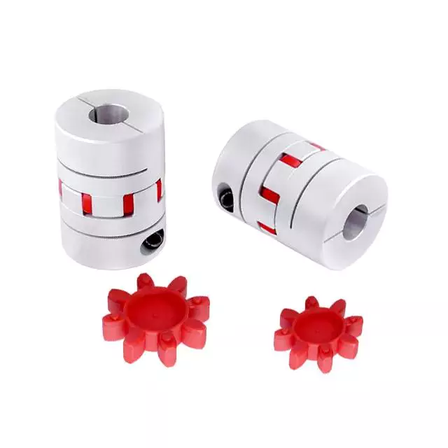
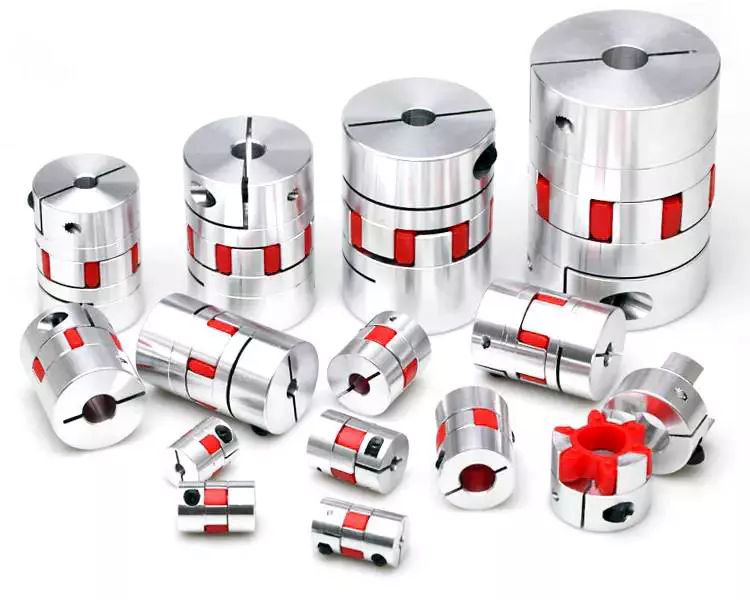
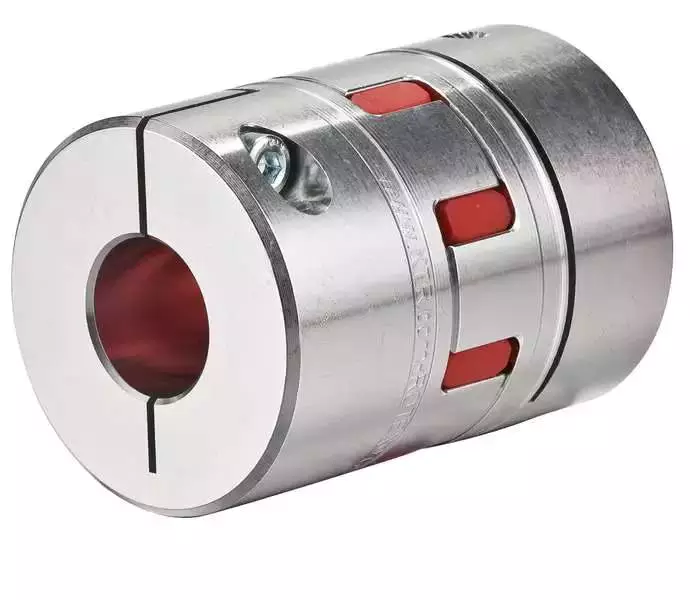
China high quality Plum Style Clamp Flexible Jaw Spider H Type CZPT with high quality

Item Description

I.Quick Introduction
Plum blossom sort elastic shaft coupling is created up of semi-shaft coupling with the identical protruding claw and elastic component. Employing the plum blossom elastic ingredient place amongst the protruding claw and 2 half shaft coupling to understand the connection of 2 semiaxis devices.
II.Application
Adaptable coupling largely utilised for commence regularly,rotating,high-velocity,medium torque and substantial reliability in the workplace. Such as:mining and metallurgy,mine,petroleum,chemical,market,obese,transportation,mild sector,weaving,water pump,supporter,etc. Operate environment -35~ —- —- B a hundred and ten B 125 B 140 .017 .571 .038 — — B 160 B one hundred eighty B 200 .059 .092 .fourteen — — B 225 B 250 B 280 .21 .29 .41 -forty four forty seven -forty four 52 A one hundred ten A a hundred twenty five A one hundred forty .017 .571 .038 — — A one hundred sixty A one hundred eighty A two hundred .059 .092 .fourteen — — A 225 A 250 A 280 .21 .29 .41 -forty four forty seven -thirty fifty two A 315 .58 5500 2150 47 88 a hundred one hundred twenty 44 88 a hundred 120 A 350 .81 7700 1950 59 88 110 one hundred forty fifty nine 88 110 a hundred and forty A 400 one.1 10300 1700 sixty four 98 a hundred and twenty a hundred and fifty sixty four 98 a hundred and twenty one hundred fifty A 440 one.4 13500 1550 seventy eight 118 a hundred thirty one hundred sixty 78 118 one hundred thirty one hundred sixty A 480 one.seven 16600 1400 88 134 one hundred forty five one hundred eighty 88 134 one hundred forty five a hundred and eighty A 520 2.two 21200 1300 98 138 150 one hundred ninety ninety eight 138 a hundred and fifty 190 A 560 A 610 A 660 A 710 three 4 5.1 6.5 29000 38000 49000 62000


Our Companies
one. Practical: 24th Several hours sales/Right after-revenue Services on-line or on the mobile phone
two. Quality Assurance: We will go over with you and offer you the ideal high quality comfortable to your marketplace
3. Swift shipping and delivery: Time is cash, we guarantee we usually will produce the goods quicker than other people
4.According to customers’ drawing,tailored technical specs are welcomed
five.Low MOQ,small orders can be acknowledged.
About us
Zhalaiteqi Xihu (West Lake) Dis. Mechanical seals part Co.,ltd is 1 of professional manufacturer , planning and generating rubber oil seals, hydraulic seals, mechanical seals,bearing,O-rings, PTFE gasket,etc. these goods are extensively used in automotive, heavy truck, agriculture machinery, building equipment , Our business have  sturdy ability in  method R&D and rich encounter in productions. We have 5 several years encounter.
We constantly insist on its foothold Products Top quality IS Vital TO AN Business and we will proceed to persist on Quality First, CREDITABILITY FIST principle, concentrate on checking out and producing, try out our greatest to proving first-class merchandise and very best services to satisfy our customers’ requirements
Welcome to make contact with us If your have any concerns !
 

N-EUPEX Kupplung Coupling AccoupleAccouple-ment Bau-Größe art Size T T illType Taille Nenn-wert Nominal value C té value Caracté-ristiqueristique 1) PN n Nenn-dreh-moment Nom. t Nom. torque CoupleCouple nomin. TNTN Nm Dreh-zahl Speed Vit S eed Vitesse n max min-1 BohrunAlésage D1 Teil / Par1 3) bis to jusqu’à mm g / Bore t / Partie 4 + 2 3) bis to jusqu’à mm da mm d2 Teil Part Pti Part Partie 1 4 2 mm mm
B 58 B 68 B 80 B 95 0.002 0.0036 0.0063 0.011 19 34 60 100 5000 5000 5000 5000 —- 19 24 30 42 —- 24 28 38 42
B 110 B 125 B 140 0.017 0.025 0.038 160 240 360 5000 5000 4900 48 55 60 48 55 60
B 160 B 180 B 200 0.059 0.092 0.14 560 880 1340 4250 3800 3400 65 75 85 65 75 85
B 225 B 250 B 280 0.21 0.29 0.41 2000 2800 3900 3000 2750 2450 -44 47 90 100 110 -44 52 90 100 110
A 110 A 125 A 140 0.017 0.025 0.038 160 240 360 5000 5000 4900 48 55 60 38 45 50
A 160 A 180 A 200 0.059 0.092 0.14 560 880 1340 4250 3800 3400 65 75 85 58 65 75
A 225 A 250 A 280 0.21 0.29 0.41 2000 2800 3900 3000 2750 2450 -44 47 90 100 110 -30 52 85 95 105
A 315 0.58 5500 2150 47 88 100 120 44 88 100 120
A 350 0.81 7700 1950 59 88 110 140 59 88 110 140
A 400 1.1 10300 1700 64 98 120 150 64 98 120 150
A 440 1.4 13500 1550 78 118 130 160 78 118 130 160
A 480 1.7 16600 1400 88 134 145 180 88 134 145 180
A 520 2.2 21200 1300 98 138 150 190 98 138 150 190
A 560 A 610 A 660 A 710 3 4 5.1 6.5 29000 38000 49000 62000

###

Type Max torque
N.m
Max speed
r/min
D D 1 d 1 L C n-M   kg
FCL90 4 4000 90 35.5 11 28 3 4-M8×50 1.7
FCL100 10 4000 100 40 11 35.5 3 4-M10×56 2.3
FCL112 16 4000 112 45 13 40 3 4-M10×56 2.8
FCL125 25 4000 125 50 13 45 3 4-M12×64 4.0
FCL140 50 4000 140 63 13 50 3 6-M12×64 5.4
FCL160 110 4000 160 80 15 56 3 8-M12×64 8.0
FCL180 157 3500 180 90 15 63 3 8-M12×64 10.5
FCL200 245 3200 200 100 21 71 4 8-M20×85 16.2
FCL224 392 2850 224 112 21 80 4 8-M20×85 21.3
FCL220 618 2550 250 125 25 90 4 8-M24×110 31.6
FCL280 980 2300 280 140 34 100 4 8-M24×116 44.0
FCL315 1568 2050 315 160 41 112 4 10-M24×116 57.7
FCL355 2450 1800 355 180 60 125 5 8-M30×50 89.5
FCL400 3920 1600 400 200 60 125 5 10-M30×150 113
FCL450 6174 1400 450 224 65 140 5 12-M30×150 145
FCL560 9800 1150 560 250 85 160 5 14-M30×150 229
FCL630 15680 1000 630 280 95 180 5 18-M30×150 296

###

TYPE Allowable Wrench Torque (N.m) Max (rpm) Max Bore (mm) Out Dia (mm) Total Length (mm) L1 (mm) Weight (kg)
L-035 0.15 6000 8 16.1 20.15 6.68 0.02
L-050 0.45 4500 16 27.6 42.55 15.60 0.14
L-070 0.9 3600 20 34.3 49.92 19.30 0.25
L-075 1.5 3600 26 44.6 52.88 20.60 0.45
L-090 2.4 3000 28 53.6 53.22 20.70 50.66
L-095 3 3000 28 53.6 62.36 25.20 0.78
L-100 7.5 3000 36 64.6 86.47 34.70 1.53
L-110 15 2500 38 84.3 106.32 43.10 3.3
L-150 30 2500 46 95.3 112.95 44.60 4.48
L-190 45 2000 58 115 138.50 56.00 9.14

How to Identify a Faulty Drive Shaft

The most common problems associated with automotive driveshafts include clicking and rubbing noises. While driving, the noise from the driver’s seat is often noticeable. An experienced auto mechanic can easily identify whether the sound is coming from both sides or from one side. If you notice any of these signs, it’s time to send your car in for a proper diagnosis. Here’s a guide to determining if your car’s driveshaft is faulty:
air-compressor

Symptoms of Driveshaft Failure

If you’re having trouble turning your car, it’s time to check your vehicle’s driveshaft. A bad driveshaft can limit the overall control of your car, and you should fix it as soon as possible to avoid further problems. Other symptoms of a propshaft failure include strange noises from under the vehicle and difficulty shifting gears. Squeaking from under the vehicle is another sign of a faulty driveshaft.
If your driveshaft fails, your car will stop. Although the engine will still run, the wheels will not turn. You may hear strange noises from under the vehicle, but this is a rare symptom of a propshaft failure. However, you will have plenty of time to fix the problem. If you don’t hear any noise, the problem is not affecting your vehicle’s ability to move.
The most obvious signs of a driveshaft failure are dull sounds, squeaks or vibrations. If the drive shaft is unbalanced, it is likely to damage the transmission. It will require a trailer to remove it from your vehicle. Apart from that, it can also affect your car’s performance and require repairs. So if you hear these signs in your car, be sure to have it checked by a mechanic right away.

Drive shaft assembly

When designing a propshaft, the design should be based on the torque required to drive the vehicle. When this torque is too high, it can cause irreversible failure of the drive shaft. Therefore, a good drive shaft design should have a long service life. Here are some tips to help you design a good driveshaft. Some of the main components of the driveshaft are listed below.
Snap Ring: The snap ring is a removable part that secures the bearing cup assembly in the yoke cross hole. It also has a groove for locating the snap ring. Spline: A spline is a patented tubular machined element with a series of ridges that fit into the grooves of the mating piece. The bearing cup assembly consists of a shaft and end fittings.
U-joint: U-joint is required due to the angular displacement between the T-shaped housing and the pinion. This angle is especially large in raised 4x4s. The design of the U-joint must guarantee a constant rotational speed. Proper driveshaft design must account for the difference in angular velocity between the shafts. The T-bracket and output shaft are attached to the bearing caps at both ends.
air-compressor

U-joint

Your vehicle has a set of U-joints on the driveshaft. If your vehicle needs to be replaced, you can do it yourself. You will need a hammer, ratchet and socket. In order to remove the U-joint, you must first remove the bearing cup. In some cases you will need to use a hammer to remove the bearing cup, you should be careful as you don’t want to damage the drive shaft. If you cannot remove the bearing cup, you can also use a vise to press it out.
There are two types of U-joints. One is held by a yoke and the other is held by a c-clamp. A full ring is safer and ideal for vehicles that are often used off-road. In some cases, a full circle can be used to repair a c-clamp u-joint.
In addition to excessive torque, extreme loads and improper lubrication are common causes of U-joint failure. The U-joint on the driveshaft can also be damaged if the engine is modified. If you are driving a vehicle with a heavily modified engine, it is not enough to replace the OE U-joint. In this case, it is important to take the time to properly lubricate these components as needed to keep them functional.

tube yoke

QU40866 Tube Yoke is a common replacement for damaged or damaged driveshaft tubes. They are desirably made of a metallic material, such as an aluminum alloy, and include a hollow portion with a lug structure at one end. Tube yokes can be manufactured using a variety of methods, including casting and forging. A common method involves drawing solid elements and machining them into the final shape. The resulting components are less expensive to produce, especially when compared to other forms.
The tube fork has a connection point to the driveshaft tube. The lug structure provides attachment points for the gimbal. Typically, the driveshaft tube is 5 inches in diameter and the lug structure is 4 inches in diameter. The lug structure also serves as a mounting point for the drive shaft. Once installed, Tube Yoke is easy to maintain. There are two types of lug structures: one is forged tube yoke and the other is welded.
Heavy-duty series drive shafts use bearing plates to secure the yoke to the U-joint. All other dimensions are secured with external snap rings. Yokes are usually machined to accept U-bolts. For some applications, grease fittings are used. This attachment is more suitable for off-road vehicles and performance vehicles.
air-compressor

end yoke

The end yoke of the drive shaft is an integral part of the drive train. Choosing a high-quality end yoke will help ensure long-term operation and prevent premature failure. Pat’s Driveline offers a complete line of automotive end yokes for power take-offs, differentials and auxiliary equipment. They can also measure your existing parts and provide you with high quality replacements.
A U-bolt is an industrial fastener with threaded legs. When used on a driveshaft, it provides greater stability in unstable terrain. You can purchase a U-bolt kit to secure the pinion carrier to the drive shaft. U-bolts also come with lock washers and nuts. Performance cars and off-road vehicles often use this type of attachment. But before you install it, you have to make sure the yoke is machined to accept it.
End yokes can be made of aluminum or steel and are designed to provide strength. It also offers special bolt styles for various applications. CZPT’s drivetrain is also stocked with a full line of automotive flange yokes. The company also produces custom flanged yokes for many popular brands. Since the company has a comprehensive line of replacement flange yokes, it can help you transform your drivetrain from non-serviceable to serviceable.

bushing

The first step in repairing or replacing an automotive driveshaft is to replace worn or damaged bushings. These bushings are located inside the drive shaft to provide a smooth, safe ride. The shaft rotates in a rubber sleeve. If a bushing needs to be replaced, you should first check the manual for recommendations. Some of these components may also need to be replaced, such as the clutch or swingarm.

China manufacturer Plastic PPR CZPT Fitting CZPT 20-60 mm PPR Cap with high quality

Item Description

Name

ppr pipe fittings

Color

green

Connection

socket fusion joint, electro fusion joint or transition joint 

Material

random polypropylene 

Resistance to high temperature

Below 40ºC

Service life

50 years

Tensile yield strength MPa ≥40Mpa
Vicat softening temperature ºC ≥79
Falling weight impact test TIR ≤10

Longitudinal reversion

≤5%

How to Determine the Quality of a Worm Shaft

There are many advantages of a worm shaft. It is easier to manufacture, as it does not require manual straightening. Among these benefits are ease of maintenance, reduced cost, and ease of installation. In addition, this type of shaft is much less prone to damage due to manual straightening. This article will discuss the different factors that determine the quality of a worm shaft. It also discusses the Dedendum, Root diameter, and Wear load capacity.
worm shaft

Root diameter

There are various options when choosing worm gearing. The selection depends on the transmission used and production possibilities. The basic profile parameters of worm gearing are described in the professional and firm literature and are used in geometry calculations. The selected variant is then transferred to the main calculation. However, you must take into account the strength parameters and the gear ratios for the calculation to be accurate. Here are some tips to choose the right worm gearing.
The root diameter of a worm gear is measured from the center of its pitch. Its pitch diameter is a standardized value that is determined from its pressure angle at the point of zero gearing correction. The worm gear pitch diameter is calculated by adding the worm’s dimension to the nominal center distance. When defining the worm gear pitch, you have to keep in mind that the root diameter of the worm shaft must be smaller than the pitch diameter.
Worm gearing requires teeth to evenly distribute the wear. For this, the tooth side of the worm must be convex in the normal and centre-line sections. The shape of the teeth, referred to as the evolvent profile, resembles a helical gear. Usually, the root diameter of a worm gear is more than a quarter inch. However, a half-inch difference is acceptable.
Another way to calculate the gearing efficiency of a worm shaft is by looking at the worm’s sacrificial wheel. A sacrificial wheel is softer than the worm, so most wear and tear will occur on the wheel. Oil analysis reports of worm gearing units almost always show a high copper and iron ratio, suggesting that the worm’s gearing is ineffective.

Dedendum

The dedendum of a worm shaft refers to the radial length of its tooth. The pitch diameter and the minor diameter determine the dedendum. In an imperial system, the pitch diameter is referred to as the diametral pitch. Other parameters include the face width and fillet radius. Face width describes the width of the gear wheel without hub projections. Fillet radius measures the radius on the tip of the cutter and forms a trochoidal curve.
The diameter of a hub is measured at its outer diameter, and its projection is the distance the hub extends beyond the gear face. There are two types of addendum teeth, one with short-addendum teeth and the other with long-addendum teeth. The gears themselves have a keyway (a groove machined into the shaft and bore). A key is fitted into the keyway, which fits into the shaft.
Worm gears transmit motion from two shafts that are not parallel, and have a line-toothed design. The pitch circle has two or more arcs, and the worm and sprocket are supported by anti-friction roller bearings. Worm gears have high friction and wear on the tooth teeth and restraining surfaces. If you’d like to know more about worm gears, take a look at the definitions below.
worm shaft

CZPT’s whirling process

Whirling process is a modern manufacturing method that is replacing thread milling and hobbing processes. It has been able to reduce manufacturing costs and lead times while producing precision gear worms. In addition, it has reduced the need for thread grinding and surface roughness. It also reduces thread rolling. Here’s more on how CZPT whirling process works.
The whirling process on the worm shaft can be used for producing a variety of screw types and worms. They can produce screw shafts with outer diameters of up to 2.5 inches. Unlike other whirling processes, the worm shaft is sacrificial, and the process does not require machining. A vortex tube is used to deliver chilled compressed air to the cutting point. If needed, oil is also added to the mix.
Another method for hardening a worm shaft is called induction hardening. The process is a high-frequency electrical process that induces eddy currents in metallic objects. The higher the frequency, the more surface heat it generates. With induction heating, you can program the heating process to harden only specific areas of the worm shaft. The length of the worm shaft is usually shortened.
Worm gears offer numerous advantages over standard gear sets. If used correctly, they are reliable and highly efficient. By following proper setup guidelines and lubrication guidelines, worm gears can deliver the same reliable service as any other type of gear set. The article by Ray Thibault, a mechanical engineer at the University of Virginia, is an excellent guide to lubrication on worm gears.

Wear load capacity

The wear load capacity of a worm shaft is a key parameter when determining the efficiency of a gearbox. Worms can be made with different gear ratios, and the design of the worm shaft should reflect this. To determine the wear load capacity of a worm, you can check its geometry. Worms are usually made with teeth ranging from one to four and up to twelve. Choosing the right number of teeth depends on several factors, including the optimisation requirements, such as efficiency, weight, and centre-line distance.
Worm gear tooth forces increase with increased power density, causing the worm shaft to deflect more. This reduces its wear load capacity, lowers efficiency, and increases NVH behavior. Advances in lubricants and bronze materials, combined with better manufacturing quality, have enabled the continuous increase in power density. Those three factors combined will determine the wear load capacity of your worm gear. It is critical to consider all three factors before choosing the right gear tooth profile.
The minimum number of gear teeth in a gear depends on the pressure angle at zero gearing correction. The worm diameter d1 is arbitrary and depends on a known module value, mx or mn. Worms and gears with different ratios can be interchanged. An involute helicoid ensures proper contact and shape, and provides higher accuracy and life. The involute helicoid worm is also a key component of a gear.
Worm gears are a form of ancient gear. A cylindrical worm engages with a toothed wheel to reduce rotational speed. Worm gears are also used as prime movers. If you’re looking for a gearbox, it may be a good option. If you’re considering a worm gear, be sure to check its load capacity and lubrication requirements.
worm shaft

NVH behavior

The NVH behavior of a worm shaft is determined using the finite element method. The simulation parameters are defined using the finite element method and experimental worm shafts are compared to the simulation results. The results show that a large deviation exists between the simulated and experimental values. In addition, the bending stiffness of the worm shaft is highly dependent on the geometry of the worm gear toothings. Hence, an adequate design for a worm gear toothing can help reduce the NVH (noise-vibration) behavior of the worm shaft.
To calculate the worm shaft’s NVH behavior, the main axes of moment of inertia are the diameter of the worm and the number of threads. This will influence the angle between the worm teeth and the effective distance of each tooth. The distance between the main axes of the worm shaft and the worm gear is the analytical equivalent bending diameter. The diameter of the worm gear is referred to as its effective diameter.
The increased power density of a worm gear results in increased forces acting on the corresponding worm gear tooth. This leads to a corresponding increase in deflection of the worm gear, which negatively affects its efficiency and wear load capacity. In addition, the increasing power density requires improved manufacturing quality. The continuous advancement in bronze materials and lubricants has also facilitated the continued increase in power density.
The toothing of the worm gears determines the worm shaft deflection. The bending stiffness of the worm gear toothing is also calculated by using a tooth-dependent bending stiffness. The deflection is then converted into a stiffness value by using the stiffness of the individual sections of the worm shaft. As shown in figure 5, a transverse section of a two-threaded worm is shown in the figure.

China manufacturer Polypropylene PP French Guillemin Hose Tail CZPT with Latch with Great quality

Solution Description

Item name: Polypropylene PP  Guillemin Coupling

Common: EN 14420

Process: Injection molding

Dimension: From DN40 (1-1/2″) to DN80(3″)

Material: Polypropylene PP

Seal: EPDM

Working Pressure: 16bar/228psi

Bursting Stress: 48bar/682psi


Positive aspects:

It is utilized in business, agriculture, construction and numerous pipeline services. It is a kind of joint that can comprehend pipeline relationship or disconnection without tools. It is appropriate for rapid connection of different fluid soft and difficult pipes. It is basic to run, affordable and practical, and will save time and manpower

Specification:


HangZhou FUYIKANG Metal INDUSTRIAL CO., LTD  has a long time of encounter in cam and groove coupling, Guillemin coupling,Bauer coupling, En 14420-3 Security clamps and din2828 couplings, ferrules,and customerized goods and so on.

Contact:


Dimensions Part Number
1-1/2" DN40 PP 6804040
2" DN50 PP 6805050
3" DN80 PP 6808075
PP 6808090
Dimensions Part Number
1-1/2" DN40 PP 6804040
2" DN50 PP 6805050
3" DN80 PP 6808075
PP 6808090

The five components of an axle, their function and installation

If you’re considering replacing an axle in your vehicle, you should first understand what it is. It is the component that transmits electricity from one part to another. Unlike a fixed steering wheel, the axles are movable. The following article will discuss the five components of the half shaft, their function and installation. Hopefully you were able to identify the correct axle for your vehicle. Here are some common problems you may encounter along the way.
Driveshaft

five components

The five components of the shaft are flange, bearing surface, spline teeth, spline pitch and pressure angle. The higher the number of splines, the stronger the shaft. The maximum stress that the shaft can withstand increases with the number of spline teeth and spline pitch. The diameter of the shaft times the cube of the pressure angle and spline pitch determines the maximum stress the shaft can withstand. For extreme load applications, use axles made from SAE 4340 and SAE 1550 materials. In addition to these two criteria, spline rolling produces a finer grain structure in the material. Cutting the splines reduces the strength of the shaft by 30% and increases stress.
The asymmetric length of the shaft implies different torsional stiffness. A longer shaft, usually the driver’s side, can handle more twist angles before breaking. When the long axis is intact, the short axis usually fails, but this does not always happen. Some vehicles have short axles that permanently break, causing the same failure rate for both. It would be ideal if both shafts were the same length, they would share the same load.
In addition to the spline pitch, the diameter of the shaft spline is another important factor. The small diameter of a spline is the radius at which it resists twisting. Therefore, the splines must be able to absorb shock loads and shocks while returning to their original shape. To achieve these goals, the spline pitch should be 30 teeth or less, which is standard on Chrysler 8.75-inch and GM 12-bolt axles. However, a Ford 8.8-inch axle may have 28 or 31 tooth splines.
In addition to the CV joints, the axles also include CV joints, which are located on each end of the axle. ACV joints, also known as CV joints, use a special type of bearing called a pinion. This is a nut that meshes with the side gear to ensure proper shaft alignment. If you notice a discrepancy, take your car to a shop and have it repaired immediately.

Function

Axles play several important roles in a vehicle. It transfers power from the transmission to the rear differential gearbox and the wheels. The shaft is usually made of steel with cardan joints at both ends. Shaft Shafts can be stationary or rotating. They are all creatures that can transmit electricity and loads. Here are some of their functions. Read on to learn more about axles. Some of their most important features are listed below.
The rear axle supports the weight of the vehicle and is connected to the front axle through the axle. The rear axle is suspended from the body, frame and axle housing, usually spring loaded, to cushion the vehicle. The driveshaft, also called the propshaft, is located between the rear wheels and the differential. It transfers power from the differential to the drive wheels.
The shaft is made of mild steel or alloy steel. The latter is stronger, more corrosion-resistant and suitable for special environments. Forged for large diameter shafts. The cross section of the shaft is circular. While they don’t transmit torque, they do transmit bending moment. This allows the drive train to rotate. If you’re looking for new axles, it’s worth learning more about how they work.
The shaft consists of three distinct parts: the main shaft and the hub. The front axle assembly has a main shaft, while the rear axle is fully floating. Axles are usually made of chrome molybdenum steel. The alloy’s chromium content helps the axle maintain its tensile strength even under extreme conditions. These parts are welded into the axle housing.
Driveshaft

Material

The material used to make the axle depends on the purpose of the vehicle. For example, overload shafts are usually made of SAE 4340 or 1550 steel. These steels are high strength low alloy alloys that are resistant to bending and buckling. Chromium alloys, for example, are made from steel and have chromium and molybdenum added to increase their toughness and durability.
The major diameter of the shaft is measured at the tip of the spline teeth, while the minor diameter is measured at the bottom of the groove between the teeth. These two diameters must match, otherwise the half shaft will not work properly. It is important to understand that the brittleness of the material should not exceed what is required to withstand normal torque and twisting, otherwise it will become unstable. The material used to make the axles should be strong enough to carry the weight of a heavy truck, but must also be able to withstand torque while still being malleable.
Typically, the shaft is case hardened using an induction process. Heat is applied to the surface of the steel to form martensite and austenite. The shell-core interface transitions from compression to tension, and the peak stress level depends on the process variables used, including heating time, residence time, and hardenability of the steel. Some common materials used for axles are listed below. If you’re not sure which material is best for your axle, consider the following guide.
The axle is the main component of the axle and transmits the transmission motion to the wheels. In addition, they regulate the drive between the rear hub and the differential sun gear. The axle is supported by axle bearings and guided to the path the wheels need to follow. Therefore, they require proper materials, processing techniques and thorough inspection methods to ensure lasting performance. You can start by selecting the material for the shaft.
Choosing the right alloy for the axle is critical. You will want to find an alloy with a low carbon content so it can harden to the desired level. This is an important consideration because the hardenability of the alloy is important to the durability and fatigue life of the axle. By choosing the right alloy, you will be able to minimize these problems and improve the performance of your axle. If you have no other choice, you can always choose an alloy with a higher carbon content, but it will cost you more money.
Driveshaft

Install

The process of installing a new shaft is simple. Just loosen the axle nut and remove the set bolt. You may need to tap a few times to get a good seal. After installation, check the shaft at the points marked “A” and “D” to make sure it is in the correct position. Then, press the “F” points on the shaft flange until the points are within 0.002″ of the runout.
Before attempting to install the shaft, check the bearings to make sure they are aligned. Some bearings may have backlash. To determine the amount of differential clearance, use a screwdriver or clamp lever to check. Unless it’s caused by a loose differential case hub, there shouldn’t be any play in the axle bearings. You may need to replace the differential case if the axles are not mounted tightly. Thread adjusters are an option for adjusting drive gear runout. Make sure the dial indicator is mounted on the lead stud and loaded so that the plunger is at right angles to the drive gear.
To install the axle, lift the vehicle with a jack or crane. The safety bracket should be installed under the frame rails. If the vehicle is on a jack, the rear axle should be in the rebound position to ensure working clearance. Label the drive shaft assemblies and reinstall them in their original positions. Once everything is back in place, use a 2-jaw puller to pry the yoke and flange off the shaft.
If you’ve never installed a half shaft before, be sure to read these simple steps to get it right. First, check the bearing surfaces to make sure they are clean and undamaged. Replace them if they look battered or dented. Next, remove the seal attached to the bushing hole. Make sure the shaft is installed correctly and the bearing surfaces are level. After completing the installation process, you may need to replace the bearing seals.

China OEM Circular Saws and Belt Saws Gearboxes – Replacement of Comer Code T-19G near me factory

Circular Saws and Belt Saws Gearboxes – Replacement of Comer Code T-19G

Description Circular Saws and Belt Saws Gearboxes – Replacement of Comer Code T-19G
Application
  • Various (agricultural) applications
  • Multi-row rotary tillers
  • Mowers
  • Fertiliser spreaders
  • Band saws
Consists of
  • Gearbox
  • Without oil
Technical information
  • If you have any questions regarding performance at different speeds, please do not hesitate to contact us
  • When using for the first time, replace the oil after 50 operating hours
Max. input power 12.5 kW
Max. output torque 27.8 daNm
Contains oil No
Max. oil capacity 0.9 l
Max. oil change interval 500 h
Oil SAE viscosity grade 80W-90
Housing material Cast iron GG25
Weight 14 kg
Gear arrangement Increasing 33 – 34
Gear ratio 1:1.84
Input power kW / HP Increasing 12.5 / 17 kW/HP
Input shaft Increasing Z
Input shaft Reducing X – Y
Input power KW / HP Reducing 8.8 / 12 kW/HP
Output Torque DaNm Increasing 11.6 daNm
Ratio Increasing 1 : 1.84
Ratio Reducing 1,84 : 1
Input section Z
Shaft X 30 (B)
Shaft Y 30 (B)
Shaft Z 1 3/8″ (6) (C)