Product Description
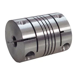
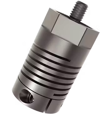
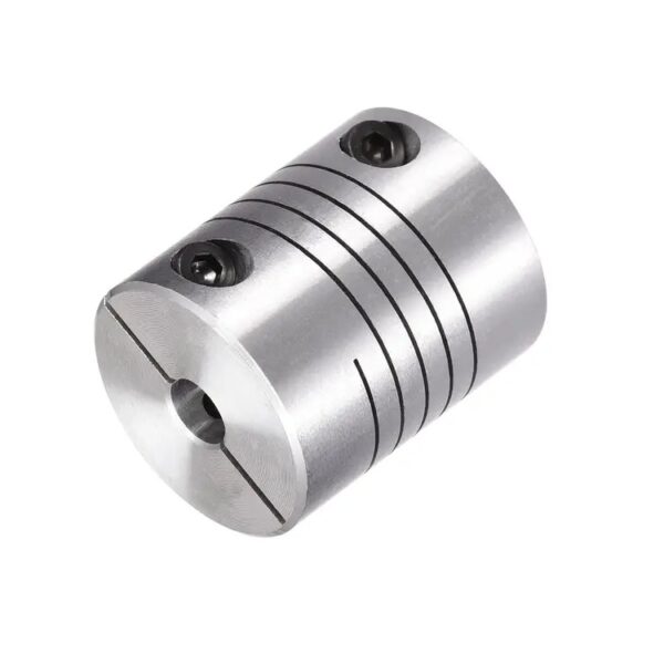
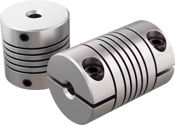
A beam coupling, also known as helical coupling, is a flexible coupling for transmitting torque between 2 shafts while allowing for angular misalignment, parallel offset and even axial motion, of 1 shaft relative to the other. This design utilizes a single piece of material and becomes flexible by removal of material along a spiral path resulting in a curved flexible beam of helical shape. Since it is made from a single piece of material, the Beam Style coupling does not exhibit thebacklash found in some multi-piece couplings. Another advantage of being an all machined coupling is the possibility to incorporate features into the final product while still keep the single piece integrity.
Changes to the lead of the helical beam provide changes to misalignment capabilities as well as other performance characteristics such as torque capacity and torsional stiffness. It is even possible to have multiple starts within the same helix.
The material used to manufacture the beam coupling also affects its performance and suitability for specific applications such as food, medical and aerospace. Materials are typically aluminum alloy and stainless steel, but they can also be made in acetal, maraging steel and titanium. The most common applications are attaching encoders to shafts and motion control for robotics.
Please contact us to learn more.
| Type | Description | Bore(mm) |
| BR | D18L25 | 4~6.35 |
| D20L25 | 4~8 | |
| D25L30 | 5~12 | |
| D32L40 | 8~16 | |
| DR | D12L19 | 3~6 |
| D16L24 | 3~6.35 | |
| D18L25 | 3~10 | |
| D25L30 | 5~14 | |
| BE | D16L23 | 3~6 |
| D18L25 | 3~6.35 | |
| D20L26 | 4~8 | |
| D25L31 | 5~12 | |
| D32L41 | 6~16 |
/* January 22, 2571 19:08:37 */!function(){function s(e,r){var a,o={};try{e&&e.split(“,”).forEach(function(e,t){e&&(a=e.match(/(.*?):(.*)$/))&&1
Challenges Arising from Misaligned Helical Couplings and Their Resolution
Misaligned helical couplings can lead to several challenges that affect the performance and longevity of machinery:
- Reduced Torque Transmission: Angular misalignment in helical couplings can result in reduced torque transmission efficiency, leading to power loss and decreased overall machinery performance.
- Excessive Wear: Continuous operation with misaligned couplings can cause increased wear on both the coupling and connected components, resulting in premature failure and the need for frequent maintenance.
- Vibration and Noise: Misaligned couplings can generate vibration and noise due to uneven torque distribution and irregular motion, negatively impacting machinery operation and operator comfort.
- Heat Generation: Misalignment can lead to increased friction and heat generation at the coupling interface, potentially causing damage to the coupling material and affecting surrounding components.
To address these challenges, it’s crucial to:
- Regularly Inspect and Align: Perform routine inspections to identify any misalignment issues. If misalignment is detected, realign the couplings to ensure proper shaft alignment.
- Use Flexible Couplings: Choose helical couplings specifically designed to accommodate misalignment. These couplings provide flexibility and self-alignment features, reducing the impact of misalignment.
- Implement Precision Installation: During installation, carefully align the shafts using precision tools and techniques. Avoid forceful installation that could introduce misalignment.
- Monitor Operating Conditions: Regularly monitor machinery operation to detect any abnormal vibration, noise, or performance changes that could indicate misalignment issues.
By addressing misalignment challenges promptly and following best practices, you can ensure the proper functioning and longevity of helical couplings and the machinery they are installed in.
Considerations for Choosing a Helical Coupling for Your Application
When selecting a helical coupling for a specific application, several key factors should be considered:
- Torque Capacity: Determine the maximum torque that the coupling will need to transmit in your application. Choose a coupling with a torque capacity that exceeds the application’s requirements.
- Shaft Size: Ensure that the coupling’s bore size matches the diameter of the shafts to be connected. Proper sizing prevents slippage and ensures efficient torque transmission.
- Angular Misalignment: Evaluate the degree of angular misalignment that the coupling needs to accommodate. Different couplings have varying angular misalignment capabilities.
- Radial Misalignment: Consider the amount of radial misalignment that the coupling must handle. Choose a coupling that can accommodate the expected radial displacement.
- Axial Misalignment: If there will be axial movement between the shafts, select a coupling that can handle the required axial displacement without binding.
- Environmental Conditions: Take into account the operating environment, including temperature, humidity, dust, and chemical exposure. Choose a coupling material that is suitable for the conditions.
- Speed: Determine the rotational speed of the shafts. Ensure that the chosen coupling is rated for the application’s speed without causing resonance or vibration issues.
- Backlash: Assess the acceptable level of backlash in your application. Some couplings have minimal backlash, which is critical for precision applications.
- Cost: Consider the budget for your project. While it’s important to choose a reliable coupling, also balance the cost with the performance requirements.
By carefully evaluating these factors and consulting with coupling manufacturers or experts, you can choose the right helical coupling that meets the needs of your specific application.
Elaboration on Torsional Stiffness in Relation to Helical Couplings and Its Significance
Torsional stiffness refers to the resistance of a helical coupling to twisting or rotational deformation under a certain amount of torque. It is a crucial mechanical property that impacts the performance of helical couplings:
- Response to Torque: A coupling with higher torsional stiffness can transmit torque more efficiently and accurately, resulting in better power transmission.
- Reduced Torsional Deflection: High torsional stiffness minimizes torsional deflection, which is the angular twist experienced by the coupling under torque. This is especially important in precision applications where accurate angular positioning is required.
- Minimized Backlash: Torsional stiffness helps reduce backlash, which is the angular play or movement between connected shafts when the direction of torque changes.
- Dynamic Performance: Torsional stiffness contributes to the coupling’s ability to respond quickly to changes in torque, making it suitable for applications with rapidly changing loads.
- Vibration Damping: While helical couplings provide some level of flexibility to accommodate misalignment, their torsional stiffness helps dampen vibrations and resonances.
- Torsional Resonances: In applications where torsional resonances can occur, a well-matched torsional stiffness can help avoid critical speeds and potential mechanical failures.
When selecting a helical coupling, considering its torsional stiffness in relation to the application’s torque requirements and performance demands is essential to ensure optimal functionality and durability.


editor by CX 2024-04-12
China Custom Helical Drive Flexible Coupling for Encoder Shaft Coupling
Product Description
Helical Drive Flexible Coupling For Encoder Shaft Coupling Dimensions
Product Description
Coupling refers to a device that connects 2 shafts or shafts and rotating parts, rotates together during the transmission of motion and power, and does not disengage under normal conditions. Sometimes it is also usedas a safety device to prevent the connected parts from bearing excessive load, which plays the role of overload protection.
Couplings can be divided into rigid couplings and flexible couplings. Rigid couplings do not have buffering property and the ability to compensate the relative displacement of 2 axes. It is required that the 2 axes be strictly aligned. However, such couplings are simple in structure, low in manufacturing cost, convenient in assembly and disassembly, and maintenance, which can ensure that the 2 axes are relatively neutral, have large transmission torque, and are widely used. Commonly used are flange coupling, sleeve coupling and jacket coupling.
Flexible coupling can also be divided into flexible coupling without elastic element and flexible coupling with elastic element. The former type only has the ability to compensate the relative displacement of 2 axes, but cannot cushion and reduce vibration. Common types include slider coupling, gear coupling, universal coupling and chain coupling; The latter type contains elastic elements. In addition to the ability to compensate the relative displacement
of 2 axes, it also has the functions of buffering and vibration reduction.
Our leading mainly including universal couplings, drum gear couplings, elastic couplings etc.
Main production equipments:
Large lathe, surface grinder, milling machine, spline milling machine, horizontal broaching machine, gear hobbing machine, shaper, slotting machine, bench drilling machine, radial drilling machine, boring machine, band sawing machine, horizontal lathe, end milling machine, crankshaft grinder, CNC milling machine, etc.
Coupling performance
1) Mobility. The movability of the coupling refers to the ability to compensate the relative displacement of 2 rotating components. Factors such as manufacturing and installation errors between connected components, temperature changes during operation and deformation under load all put CHINAMFG requirements for mobility. The movable performance compensates or alleviates the additional load between shafts, bearings, couplings and other components caused by the relative displacement between rotating components.
(2) Buffering. For the occasions where the load is often started or the working load changes, the coupling shall be equipped with elastic elements that play the role of cushioning and vibration reduction to protect the prime mover and the working machine from little or no damage.
(3) Safe, reliable, with sufficient strength and service life.
(4) Simple structure, easy to assemble, disassemble and maintain.
Inspection equipment:
Dynamic balance tester, high-speed intelligent carbon and sulfur analyzer, Blochon optical hardness tester, Leeb hardness tester, magnetic yoke flaw detector etc.
It is widely used in metallurgical steel rolling, wind power, hydropower, mining, engineering machinery, petrochemical, lifting, paper making, rubber, rail transit, shipbuilding and marine engineering and other industries.
How to select the appropriate coupling type
The following items should be considered when selecting the coupling type.
1. The size and nature of the required transmission torque, the requirements for buffering and damping functions, and whether resonance may occur.
2. The relative displacement of the axes of the 2 shafts is caused by manufacturing and assembly errors, shaft load and thermal expansion deformation, and relative movement between components.
3. Permissible overall dimensions and installation methods, and necessary operating space for assembly, adjustment and maintenance. For large couplings, they should be able to be disassembled without axial movement of the shaft.
In addition, the working environment, service life, lubrication, sealing, economy and other conditions should also be considered, and a suitable coupling type should be selected by referring to the characteristics of various couplings.
If you cannot determine the type, you can contact our professional engineer.
FAQ
| Q: What is the payment method? A: We accept TT (Bank Transfer), Western Union, L/C. 1. For total amount under US$500, 100% in advance. 2. For total amount above US$500, 30% in advance, the rest before shipment. |
| Q: What is your MOQ? A: MOQ depends on our client’s needs, besides,we welcome trial order before mass-production. |
| Q: What is the production cycle? A: It varies a lot depending on product dimension,technical requirements and quantity. We always try to meet customers’ requirement by adjusting our workshop schedule. |
| Q: What kind of payment terms do you accept? A: T/T, western union, etc. |
| Q: Is it possible to know how is my product going on without visiting your company? A: We will offer a detailed products schedule and send weekly reports with digital pictures and videos which show the machining progress. |
| Q: If you make poor quality goods,will you refund our fund? A: We make products according to drawings or samples strictly until them reach your 100% satisfaction. And actually we wont take a chance to do poor quality products.We are proud of keeping the spirit of good quality. |
If there’s anything we can help, please feel free to contact with us.
/* January 22, 2571 19:08:37 */!function(){function s(e,r){var a,o={};try{e&&e.split(“,”).forEach(function(e,t){e&&(a=e.match(/(.*?):(.*)$/))&&1
Challenges Arising from Misaligned Helical Couplings and Their Resolution
Misaligned helical couplings can lead to several challenges that affect the performance and longevity of machinery:
- Reduced Torque Transmission: Angular misalignment in helical couplings can result in reduced torque transmission efficiency, leading to power loss and decreased overall machinery performance.
- Excessive Wear: Continuous operation with misaligned couplings can cause increased wear on both the coupling and connected components, resulting in premature failure and the need for frequent maintenance.
- Vibration and Noise: Misaligned couplings can generate vibration and noise due to uneven torque distribution and irregular motion, negatively impacting machinery operation and operator comfort.
- Heat Generation: Misalignment can lead to increased friction and heat generation at the coupling interface, potentially causing damage to the coupling material and affecting surrounding components.
To address these challenges, it’s crucial to:
- Regularly Inspect and Align: Perform routine inspections to identify any misalignment issues. If misalignment is detected, realign the couplings to ensure proper shaft alignment.
- Use Flexible Couplings: Choose helical couplings specifically designed to accommodate misalignment. These couplings provide flexibility and self-alignment features, reducing the impact of misalignment.
- Implement Precision Installation: During installation, carefully align the shafts using precision tools and techniques. Avoid forceful installation that could introduce misalignment.
- Monitor Operating Conditions: Regularly monitor machinery operation to detect any abnormal vibration, noise, or performance changes that could indicate misalignment issues.
By addressing misalignment challenges promptly and following best practices, you can ensure the proper functioning and longevity of helical couplings and the machinery they are installed in.
Variations of Helical Couplings for Specific Uses
Helical couplings come in various variations, each designed to suit specific applications and requirements:
- Flexible Helical Couplings: These couplings are designed to provide flexibility to accommodate misalignments and torsional vibrations. They are commonly used in applications where shaft misalignment is expected.
- Rigid Helical Couplings: Rigid helical couplings are designed to provide a more solid connection between shafts, offering minimal flexibility. They are suitable for applications where precise torque transmission and accurate positioning are crucial.
- Beam Helical Couplings: Beam-style helical couplings use thin metal beams to transmit torque while allowing for some misalignment. They are often used in applications that require high torsional stiffness and minimal backlash.
- Bellows Helical Couplings: Bellows couplings use accordion-like bellows to compensate for misalignment and provide vibration damping. They are commonly used in applications that require high torsional flexibility and protection from external contaminants.
- Oldham Helical Couplings: Oldham couplings use three discs: a central disc sandwiched between two outer discs with perpendicular slots. They offer excellent misalignment compensation and are often used in motion control systems.
- Helical-Beam Couplings: These couplings combine the flexibility of beam couplings with the misalignment compensation of helical couplings. They are suitable for applications that require both flexibility and misalignment tolerance.
- Slit Helical Couplings: Slit couplings have a slit design that allows for easy installation and removal without the need to disassemble the entire system. They are commonly used in applications where frequent maintenance is required.
The availability of these variations allows engineers and designers to select the most suitable type of helical coupling based on the specific needs of their application.
Helical Couplings for High-Speed Rotation and Varying Loads
Yes, helical couplings are well-suited for applications involving high-speed rotation and varying loads. Here’s why:
Helical couplings are designed to provide flexibility and accommodate misalignment while transmitting torque between shafts. This flexibility allows them to handle the dynamic loads and vibrations that can occur in high-speed rotating systems.
When the rotational speed changes or varying loads are applied, helical couplings can absorb the resulting torsional stresses and shocks. The helical design of the coupling allows for some degree of torsional compliance, helping to mitigate the impact of sudden load changes and reducing the risk of damage to connected components.
The ability of helical couplings to handle misalignment, combined with their torsional flexibility, makes them suitable for applications where high-speed rotation and varying loads are present. However, it’s important to select the appropriate size and type of helical coupling based on the specific requirements of the application to ensure optimal performance and reliability.
Overall, helical couplings offer a versatile solution for applications that demand both high-speed rotation and the ability to accommodate changing loads and dynamic conditions.
editor by CX 2024-04-11
China Custom Original Excavator Parts Coupling CF-a Series Rubber Flexible Torsionally Steel Universal Shaft Coupling for Centaflex
Product Description
Original Excavator Parts Coupling CF-a Series Rubber Flexible Torsionally Steel Universal Shaft Coupling for Centafle
Product Display:
| Model | Outer Diameter(mm) | Inner Diameter(mm) | Hight(mm) | Diameter from Hole to Hole(mm) | Weight(kg) |
| 4A/4AS | 103 | 53 | 28 | 68 | 0.18 |
| 8A/8AS | 134 | 71 | 32 | 88 | 0.26 |
| 16A/16AS | 160 | 80 | 41 | 110 | 0.54 |
| 22A/22AS | 165 | 86 | 41 | 128 | 0.66 |
| 25A/25AS | 183 | 102 | 46 | 123 | 0.78 |
| 28A/AS | 0.88 | ||||
| 30A/30AS | 213 | 117 | 57 | 145 | 1.28 |
| 50A/50AS | 220 | 123 | 57 | 165 | 1.48 |
| 80A/80As | 225 | 120 | 65 | 167 | 1.92 |
| 90A/90As | 278 | 148 | 70 | 190 | 3.1 |
| 140A/140AS | 285 | 151 | 71 | 215 | 3.42 |
| 250A/250AS | 6.6 | ||||
| 284B | 6.34 | ||||
| 4, 4655134, EX3, ZAX460MTH, ZAX480MTH, 4636444, ZX470-3, EX470, ZAX470, ZAX450-3, ZAX450-3F, ZAX5, Atlas Copco,,
AC 385, AC 396, AC415, AC416, AC 455, AC485, AC 486, AC86, AC836, AC976, AC 6-712, 4DNV98 Chinese Brand Excavators: LGK: 6085, 200 CLG 60, 205, 220, 906, 907, 908, 920, 925, 936, CLG906C, CLG922LG YC50-8, YC60-8, YC60-8, YC135-8, YC230, YC230-8, YC230LC-8, YC360, YC85, YC50, YC85-7, YC60-7, YC135 SW50, 60, 70, 150 FR85-7, FR65, FR80, FR150-7, ZL 60, 205, 230, 360 SY55, SY60, SY215, SY230, SY210, SY220, SY310 /* March 10, 2571 17:59:20 */!function(){function s(e,r){var a,o={};try{e&&e.split(“,”).forEach(function(e,t){e&&(a=e.match(/(.*?):(.*)$/))&&1
Challenges Arising from Misaligned Helical Couplings and Their ResolutionMisaligned helical couplings can lead to several challenges that affect the performance and longevity of machinery:
To address these challenges, it’s crucial to:
By addressing misalignment challenges promptly and following best practices, you can ensure the proper functioning and longevity of helical couplings and the machinery they are installed in.
Correct Installation and Maintenance of Helical Couplings in MachineryProper installation and maintenance are essential for the optimal performance and longevity of helical couplings: Installation:
Maintenance:
By following proper installation and maintenance practices, you can maximize the performance and lifespan of helical couplings in your machinery systems.
Impact of Design and Pitch on Helical Coupling Performance and ReliabilityThe design and pitch of helical couplings play a crucial role in determining their performance and reliability: Design: The design of a helical coupling includes factors such as the number of helical elements, their shape, and the arrangement of the helix angles. A well-designed helical coupling can provide a balance between torsional stiffness and flexibility. A higher number of helical elements can increase the coupling’s torsional stiffness, making it more suitable for applications that require precise torque transmission. On the other hand, a lower number of helical elements can enhance flexibility and misalignment compensation. Pitch: The pitch of a helical coupling refers to the distance between successive helical threads. A smaller pitch results in a finer thread, offering higher torsional stiffness and accuracy in torque transmission. Couplings with a smaller pitch are often preferred for applications with precise positioning requirements. Conversely, a larger pitch provides more flexibility and misalignment compensation, making it suitable for applications with dynamic loads and vibrations. Choosing the appropriate design and pitch depends on the specific application requirements. Applications demanding high torsional stiffness and accurate torque transmission may benefit from a coupling with a smaller pitch and more helical elements. Meanwhile, applications involving misalignment accommodation and dynamic loads may favor a larger pitch and fewer helical elements to maintain flexibility and shock absorption. Ultimately, a well-matched design and pitch ensure that the helical coupling can effectively balance the need for torque transmission, misalignment compensation, and resilience to varying operating conditions, contributing to its overall performance and reliability in mechanical systems.
|