Product Description
Product Description
Internal Gear Processing
Internal Gear Ring drawing CHECK, Make Forging Mold, Forging Mold Quality Inspection Check, Machine Processing, Check Size\Hardness\Surface Finish and other technical parameters on drawing.
Inner Gear Package
Spray anti-rust oil on large internal girth Gear, Wrap waterproof cloth around , Prepare package by shaft shape & weight to choose steel frame, steel support or wooden box etc.
OEM Customized Large Inner Gear Ring
We supply OEM SERVICE, customized internal helical gear with big module, more than 1tons big weight, more than 3m length, 42CrMo/35CrMo or your specified required material inner gear ring.
Detailed Photos
Product Parameters
| Module | m | Range: 5~70 |
| Gear Teeth Number | z | OEM/Customized |
| Teeth Height | H | OEM/Customized |
| Teeth Thickness | S | OEM/Customized |
| Tooth pitch | P | OEM/Customized |
| Tooth addendum | Ha | OEM/Customized |
| Tooth dedendum | Hf | OEM/Customized |
| Working height | h’ | OEM/Customized |
| Bottom clearance | C | OEM/Customized |
| Pressure Angle | α | OEM/Customized |
| Helix Angle, | OEM/Customized | |
| Surface hardness | HRC | Range: HRC 50~HRC63(Quenching) |
| Hardness: | HB | Range: HB150~HB280; Hardening Tempering/ Hardened Tooth Surface |
| Surface finish | Range: Ra1.6~Ra3.2 | |
| Tooth surface roughness | Ra | Range: ≥0.4 |
| Gear Accuracy Grade | Grade Range: 5-6-7-8-9 (ISO 1328) | |
| Diameter | d | Range: >1m |
| Weight | Kg | Range: >100kg/ Single Piece |
| Toothed Portion Shape | internal, inner gear ring | |
| Material | Casting 42CrMo/45# steel or Customized | |
| Gear Teeth Milling | √ | |
| Gear Teeth Grinding | √ | |
| Heat Treatment | Quenching /Carburizing | |
| Sand Blasting | Null | |
| Testing | UT\MT | |
| Trademark | TOTEM/OEM | |
| Application | Gearbox, Reducer etc | |
| Transport Package | Export package (steel frame, wooden box, etc.) | |
| Origin | China | |
| HS Code | 8483409000 |
CHINAMFG SERVICE
TOTEM Machinery all the time works to supply GEAR SHAFT, ECCENTRIC SHAFT, HERRINGBONE GEAR, BEVEL GEAR, INTERNAL GEAR and other parts for transmission device & equipment (large industrial reducer & driver). Which mainly use to industrial equipment on fields of port facilities, cement, mining, metallurgical industry etc.
TOTEM Machinery invests and becomes shareholders of several machine processing factories, forging factories, casting factories, relies on these strong reliable and high-quality suppliers’ network, to let customers worry-free purchase.
TOTEM Philosophy: Quality-No.1, Integrity- No.1, Service- No.1
24hrs Salesman on-line, guarantee quick and positive feedback. Experienced and Professional Forwarder Guarantee Log. transportation.
About CHINAMFG
1. Workshop & Processing Strength
2. Testing Facilities
3. Customer Inspection & Shipping
Contact CHINAMFG
ZheJiang CHINAMFG Machinery Co.,Ltd
Facebook: ZheJiang Totem
FAQ
What’s CHINAMFG product processing progress?
Drawing CHECK, Make Forging Mold, Forging Mold Quality Inspection Check, Machine Processing, Check Size\Hardness\Surface Finish and other technical parameters on drawing.
How about TOTEM’s export package?
Spray anti-rust oil on Herringbone Gear Shaft, Wrap waterproof cloth around Gear Shaft for reducer, Prepare package by shaft shape&weight to choose steel frame, steel support or wooden box etc.
Could I customize gear\gear shaft on TOTEM?
We supply customized Gear Shaft,Eccentric Shaft,Herringbone Gear,Internal Gear,Bevel Gear with big module, more than 1tons big weight, more than 3m length, forging or casting 42CrMo/35CrMo or your specified required material.
Why can I choose TOTEM?
TOTEM has 24hrs Salesman on-line, guarantee quick and positive feedback.
TOTEM Machinery invests and becomes shareholders of several machine processing factories, forging factories, casting factories, relies on these strong reliable and high-quality supplier’s network, to let customers worry-free purchase.
Experienced and Professional Forwarder Guarantee Log. transportation.
/* March 10, 2571 17:59:20 */!function(){function s(e,r){var a,o={};try{e&&e.split(“,”).forEach(function(e,t){e&&(a=e.match(/(.*?):(.*)$/))&&1

Challenges Arising from Misaligned Helical Couplings and Their Resolution
Misaligned helical couplings can lead to several challenges that affect the performance and longevity of machinery:
- Reduced Torque Transmission: Angular misalignment in helical couplings can result in reduced torque transmission efficiency, leading to power loss and decreased overall machinery performance.
- Excessive Wear: Continuous operation with misaligned couplings can cause increased wear on both the coupling and connected components, resulting in premature failure and the need for frequent maintenance.
- Vibration and Noise: Misaligned couplings can generate vibration and noise due to uneven torque distribution and irregular motion, negatively impacting machinery operation and operator comfort.
- Heat Generation: Misalignment can lead to increased friction and heat generation at the coupling interface, potentially causing damage to the coupling material and affecting surrounding components.
To address these challenges, it’s crucial to:
- Regularly Inspect and Align: Perform routine inspections to identify any misalignment issues. If misalignment is detected, realign the couplings to ensure proper shaft alignment.
- Use Flexible Couplings: Choose helical couplings specifically designed to accommodate misalignment. These couplings provide flexibility and self-alignment features, reducing the impact of misalignment.
- Implement Precision Installation: During installation, carefully align the shafts using precision tools and techniques. Avoid forceful installation that could introduce misalignment.
- Monitor Operating Conditions: Regularly monitor machinery operation to detect any abnormal vibration, noise, or performance changes that could indicate misalignment issues.
By addressing misalignment challenges promptly and following best practices, you can ensure the proper functioning and longevity of helical couplings and the machinery they are installed in.

Utilization of Helical Couplings in Mechanical Systems
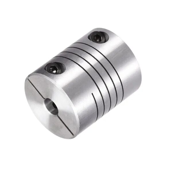
A helical coupling, also known as a beam coupling, is a type of flexible coupling that is used in mechanical systems to transmit torque and motion between shafts while accommodating misalignment. Here’s how it is utilized:
Helical couplings consist of two hubs, each with helical slots that interlock with the other hub’s slots. The interlocking design allows for flexibility in multiple directions while maintaining torsional rigidity.
When utilized in mechanical systems:
- Misalignment Compensation: Helical couplings can handle angular, axial, and parallel misalignments between shafts. The helical slots provide flexibility, allowing for small amounts of misalignment without transmitting excessive stress to connected components.
- Torque Transmission: Helical couplings transmit torque from one shaft to another while minimizing backlash. The helical slot design distributes torque evenly across the coupling’s surface, ensuring efficient power transmission.
- Reduced Vibration: The helical design of the coupling helps absorb shocks and vibrations, contributing to smoother operation and reduced wear on connected components.
- Compact Design: Helical couplings have a compact and lightweight design, making them suitable for applications with limited space.
- Simple Installation: These couplings are relatively easy to install, with minimal maintenance requirements.
- Various Applications: Helical couplings are commonly used in robotics, motion control systems, CNC machines, and other applications where precision and flexibility are essential.
In summary, helical couplings provide an effective solution for transmitting torque and motion between shafts while accommodating misalignment and reducing vibrations in various mechanical systems.

Specialized Maintenance Routines for Ensuring the Longevity of Helical Couplings
To ensure the longevity of helical couplings, consider implementing specialized maintenance routines:
- Lubrication: Proper lubrication is crucial. Use the recommended lubricant and schedule regular lubrication intervals to prevent friction and wear.
- Cleaning: Regularly clean the coupling to remove dirt, debris, and contaminants that can contribute to wear.
- Inspections: Conduct thorough visual inspections to identify signs of wear, misalignment, or damage. Regular inspections allow you to address issues early.
- Alignment Checks: Periodically check and adjust the alignment of the coupling to prevent premature wear and ensure optimal power transmission.
- Fastener Tightening: Check and tighten fasteners, such as set screws or clamping elements, to prevent loosening during operation.
- Balancing: If the coupling becomes unbalanced, have it balanced to prevent vibrations and reduce wear.
- Temperature Monitoring: Monitor the operating temperature of the coupling area. Abnormal temperature increases can indicate issues.
- Vibration Analysis: Use vibration analysis tools to monitor coupling vibrations and identify any unusual patterns.
- Replacement of Worn Parts: Replace worn or damaged parts promptly with genuine replacement components from the manufacturer.
- Record Keeping: Maintain a detailed maintenance record, including inspection dates, maintenance activities, and any issues identified.
- Training: Train maintenance personnel on proper maintenance procedures and techniques specific to helical couplings.
By following these specialized maintenance routines, you can maximize the longevity and performance of helical couplings in your machinery systems.


editor by CX 2024-02-09