Botou Ever-Power Coupling Co., Ltd.Many years of industry development, rich experience
Welcome to Botou Ever-Power Coupling Co., Ltd.!
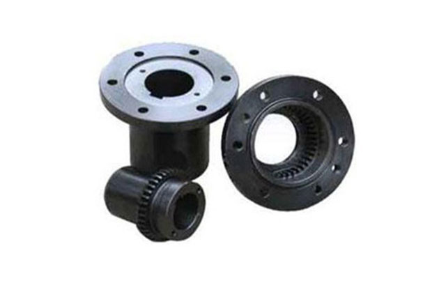
Diaphragm coupling
The factory standard model of the diaphragm coupling: TBL/TBS/TBR/TBF/TBG/TBM/TBTL/TBCL/TBCF/TBX/TBH/TBEF, etc.
The diaphragm coupling standard has the national standard: JMI/JMIJ/JMII/JMIIJ/JM/JMJ type
Diaphragm coupling Japanese standard: DJM/SJM/DJM-Z1/DJM-YN/SJM-YN/DJM-YP/SJM-YP/SJM-P type
Domestic standards for diaphragm couplings: HB/HS/HSR/HSG/HSF/HBM/HBF/HBE/HHST/ TD/GD/TGD/TDC/HGD/HBD/TDL/TDF/TDK/TDH/TDS/TDX Wait
Sample surveying and mapping, product repair, secondary dynamic balance, etc., foreign product transformation, domestic product replacement, domestic product transformation, technical support, technical drawings, product comparison, etc., can all contact us, our contact information: 0435-3565570/18626543595/ 18626543295.
Selection Guide for Diaphragm Couplings
Diaphragm couplings are mainly used in equipment directly driven by steam turbines, gas turbines and various energy recovery turbines, or in the medium and high-speed parts driven by electric motors and internal combustion engines after being accelerated by speed increasers, or directly driven by electric motors and internal combustion engines. Fans, compressors, or low-to-medium speed parts driven by various types of turbomachinery that have been decelerated by a reducer, or ultra-high speed parts used in special experimental equipment.
For general units, the TBL series should be selected first, which is simple to process and easy to disassemble and repair.
For units that require large tolerance for the shaft head, it is recommended to use the TBF series and TBG series, do not disassemble the middle section, and the connecting bolts are easy to disassemble and assemble.
For units that require large tolerance on one-sided shaft head, it is recommended to use the TBP series, which is easy to disassemble and assemble.
For units with higher requirements for additional bending moment at the shaft end, it is recommended to use the TBR series, which can achieve the minimum shaft end bending moment and has good dynamic characteristics.
The TBM series and TBS series should be preferentially selected for units with a small shaft end surface spacing, which can achieve the smallest design shaft spacing.
For couplings with ultra-high speeds, it is recommended to use TBH series ultra-high-speed diaphragm couplings. When designing and calculating, the designer will check the moment of inertia and connection strength to ensure the smooth and safe operation of the universal coupling.
Customers who have requirements for torque limitation can choose the TBX series. When the coupling reaches a fixed torque, the friction plate slips, so that the driving end and the driven end are disconnected to protect the unit from damage.
For units with insulation requirements, TBEF series and TBEP series couplings can be selected to ensure insulation safety performance.
For units with higher safety performance requirements, it is recommended to use the TBBF series and TBBG series back-tooth safety couplings. The back-tooth safety diaphragm coupling is a dual-path transmission. Under overload conditions, the built-in tooth connection contacts the auxiliary diaphragm. Transmission torque, with extraordinary safety and reliability.
For units with long shaft end faces, it is recommended to refer to TBCL series and TBCF series long-distance couplings. The middle section is welded with 20# or 16Mn to ensure welding performance. When designing and calculating, the designer will determine the critical speed and connection strength. Check to ensure the safe and stable operation of the coupling.
For units with large load impact, it is recommended to use TBTL series elastic sleeve + diaphragm combined coupling to absorb uneven impact load of the unit. The elastic sleeve coupling acts as a buffer, and the diaphragm absorbs the residual uniform load to protect the diaphragm. Injured.
Diaphragm coupling selection program
If you encounter any questions during the selection process, please feel free to consult an engineer.We suggest that the supplier and demander jointly select the model.
1. Determine the master and slave motives and working conditions, select the working condition coefficient K, and select the K value according to the coefficient table;
2. Determine the calculated power PC of the coupling;
PC=PxK
Where:
PC——calculated power (kW);
P——Transfer power (kW). Considering that the driven machine may be overloaded, it is recommended that P be calculated according to the power of the driving machine;
K-working condition coefficient.
3. Calculate the torque T transmitted by the coupling;
T=9549xPC/n
Where:
T——torque (Nm);
n——Rated or normal working speed (r/min).
4. According to the principle of: T≤nominal torque, nmax≤maximum allowable speed, combined with the selection guide, initially select the appropriate coupling model from the data sheet listed in the sample;
5. Check the conditions of use;
a: Check whether the peak torque and the maximum instantaneous torque meet the needs of the unit.For frequently started units and equipment with large starting shocks, the starting torque should be checked; for equipment with braking devices, the braking torque should be checked; if required, for equipment driven by synchronous motors or generator sets, the starting torque should be checked. The alternating torque caused by the start of the synchronous motor or the short-circuit torque of the generator.If necessary, increase the model or choose another series.
b: Whether the maximum allowable shaft diameter of the selected model can meet the requirements, the model should be enlarged or other series should be selected if necessary.
c: Whether the shaft head spacing of the unit can meet the minimum shaft head spacing requirements of the selected model.Proper shaft head spacing can not only make the coupling have better performance, but also facilitate equipment maintenance.If required, it shall comply with the relevant regulations of API610 or API671 for the distance between shaft heads.
d: Check whether the axial and angular compensation capacity of the coupling meets the needs of the unit. If necessary, increase the model or choose another series.For units with large thermal expansion, cold pre-tensioning can be used to make the flexible element of the coupling work in a state of small deformation when the unit reaches thermal equilibrium.
Working condition factor
Load type | From motivation | Driver | ||
Electric motors, steam turbines, gas turbines | Steam engine, water turbine | internal combustion engine | ||
Constant torque | Centrifugal pump, light belt conveyor, alternator, light fan | 1.0 | 1.5 | 3.0 |
Torque fluctuates slightly | Machine tools, screw compressors, screw pumps, rotary dryers | 1.5 | 2.0 | 3.5 |
Large torque fluctuations | Reciprocating pump, low viscosity mixer, crane, winch | 2.0 | 2.5 | 4.0 |
Extremely large torque fluctuations | Rotary punch, reciprocating compressor, high viscosity mixer, marine propeller | 3.0 | 3.5 | 5.0 |
According to API671 requirements, the minimum is 1.5.If necessary, the working condition coefficient can be increased or decreased according to the relevant rules of API671.
Diaphragm coupling product model description
The number of the coupling consists of five segments, for example:
TBL6-135 – YA 60*100/YB1 60*110-150 – 001
A B C D E
Section A: Represents the characteristics of the coupling and consists of letters
Section B: Represents the maximum outer diameter of the coupling
Section C: indicates the diameter and length of the shaft ends of the master and slave motor, the meaning of each letter is as follows
letter | meaning(GB3852) | letter | meaning(GB3852) |
Y J J1 Z Z1 | Y型-Long cylindrical shaft hole J型-Short cylindrical shaft hole with counterbore J1型-Short cylindrical shaft hole without counterbore Z型-Conical shaft hole with counterbore Z1型-Conical shaft hole without counterbore | A B B1 C D | A型-Flat key single keyway B型-120%oArrange flat key double keyway B1型-180%oArrange flat key double keyway C型-Conical shaft hole flat key single keyway D型-circlePillarOrdinary tangential keyway for shaped shaft hole |
Design features of diaphragm coupling
The high-performance diaphragm coupling is a flexible transmission product specially developed for high-speed rotating machinery. Its main features are simple structure, convenient disassembly and assembly, large torque transmission capacity, strong absorption of misalignment, and long life.It is suitable for units with higher speed and higher dynamic balance requirements.Such as: steam turbines, gas turbines, pumps, blowers, compressors, mills, etc.
The flexible element of the high-performance diaphragm coupling adopts a special high-strength metal diaphragm. All types of diaphragms have undergone finite element analysis and optimization by professional calculation software, and have been verified by experiments to have the best performance.The driving bolt is made of high-strength high-quality alloy steel, with a strength level of 10.9 or higher.The semi-couplings and other accessories are made of alloy steel, which has good mechanical properties after adjustment.
This sample is compiled for general industrial process application requirements. For some special and professional applications, such as various test benches, ultra-high-speed equipment and special equipment that require greater compensation capabilities, you may not be able to select a suitable one in this book. In this case, please contact our technical engineer.Our company can provide special designs according to actual requirements to meet the professional requirements of customers' special equipment.
Special instructions for diaphragm coupling
1. TBL, TBF, TBM, TBR, TBG and other series of diaphragm couplings, the flexible elements are made of high-strength stainless steel, light weight, high strength, good toughness, good corrosion resistance, long life and easy replacement.
2. The structural design and machining accuracy of the series diaphragm coupling ensure that the coupling has good dynamic balance characteristics. Care should be taken in storage, transportation and installation to ensure that the dynamic balance characteristics are not damaged.
3. The intermediate diaphragm of TBF, TBG, TBR, etc. series is disassembled as a whole, which has been dynamically balanced before leaving the factory, and it is not allowed to be disassembled outside the factory.
4. According to the specific design and working conditions of the coupling, our company can choose to perform the dynamic balance of the coupling according to the company's specifications or the corresponding procedures of the API671 standard.The factory couplings have been tested for dynamic balance, and must be aligned with the dynamic balance engraved marks during installation.
5. The maximum allowable speed listed in the sample book is the standard value given according to the structural characteristics and dynamic balance accuracy of the coupling. If higher speed and greater torque or greater centering compensation capability are required, Please consult our company's technical engineer.
6. The diaphragm part of the diaphragm coupling is extremely thin, so please protect it during transportation, installation and use to avoid bumps or scratches.
Diaphragm coupling shaft and shaft hole connection form
There are many ways to connect shafts and shaft holes, and these are our most commonly used connection methods.As shown in the following table:
letter | meaning(GB3852) | letter | meaning(GB3852) |
Y J J1 Z Z1 | Y型-Long cylindrical shaft hole J型-Short cylindrical shaft hole with counterbore J1型-Short cylindrical shaft hole without counterbore Z型-Conical shaft hole with counterbore Z1型-Conical shaft hole without counterbore | A B B1 C D | A型-Flat key single keyway B型-120%oArrange flat key double keyway B1型-180%oArrange flat key double keyway C型-Conical shaft hole flat key single keyway D型-circlePillarOrdinary tangential keyway for shaped shaft hole |
Of course, you can also choose other kinds of connection methods, such as: spline connection, expansion sleeve connection, flange connection, etc. In the sample book, we choose the most commonly used key connection as the main connection method. If there is a need for a special connection method , It is proposed in the technical agreement that the design department will make detailed changes to the design to suit the customer's connection needs.For special connection forms, please refer to the examples of other shaft head connection forms.When the cylindrical hole connection is selected, the single-key or double-key installation method refers to the recommended installation method of the half coupling.
Examples of other shaft head connection forms
1. Connection form XNUMX: Internal expansion sleeve connection. If this type of expansion sleeve connection is used for TBL series couplings, the C max size will be reduced, subject to the design size of the design department.

2. Connection form two: external expansion sleeve connection
3. Connection form XNUMX: Embedded expansion sleeve connection

4. Connection form XNUMX: flange connection
model | Allowable torque(KNm) | FK | BK(mm) | HK(mm) | DK(mm) | ZK(mm) | AK(mm) | N-D0K(mm) |
TBJ150 | 7 | according toTBLDifferent models,FKThe size is subject to change, please refer to the drawing | 12 | 3 | 130 | 150 | 158 | 12∅10H7 |
TBJ200 | 17 | 14 | 3 | 165 | 200 | 208 | 12∅12H7 | |
TBJ300 | 60 | 16 | 3 | 260 | 300 | 308 | 16∅16H7 | |
TBJ400 | 130 | 20 | 3 | 340 | 400 | 410 | 20∅20H7 | |
TBJ500 | 281 | 24 | 3 | 425 | 500 | 510 | 20∅27 H7 | |
TBJ630 | 650 | 26 | 3 | 530 | 630 | 640 | 24∅30 H7 |
5. Connection form five: hydraulic taper hole connection TBYZ hydraulic expansion sleeve is suitable for large, medium-sized or frequently disassembled connectors with large interference, such as couplings of large equipment.

Basic parameter table of TBYZ hydraulic expansion sleeve
model | Rated torqueT(kNm) | Cone combined pressurePfmax(Mpa) | Press-in forceFXmax(kN) | Demolition pressurePXmax(Mpa) | |
TBYZ120 | 0.22L | 105 | 1.53L | 155 | |
TBYZ140 | 0.29L | 105 | 1.76L | 150 | |
TBYZ160 | 0.38L | 105 | 1.99L | 145 | |
TBYZ180 | 0.47L | 105 | 2.23L | 140 | |
TBYZ200 | 0.55L | 100 | 2.56L | 135 | |
TBYZ220 | 0.66L | 100 | 2.81L | 130 | |
TBYZ240 | 0.78L | 100 | 3.05L | 128 | |
TBYZ260 | 0.92L | 100 | 3.30L | 126 | |
TBYZ280 | 1.03L | 98 | 3.68L | 122 | |
TBYZ300 | 1.18L | 98 | 3.90L | 121 | |
TBYZ320 | 1.34L | 98 | 4.18L | 120 | |
TBYZ340 | 1.51L | 98 | 4.44L | 120 | |
TBYZ360 | 1.63L | 95 | 4.80L | 118 | |
TBYZ380 | 1.82L | 95 | 5.05L | 118 |
Recommended installation method of half coupling:
According to the needs, the connection with the main and driven motor can also be designed in the form of taper hole, expansion sleeve, flange, spline, etc.When using cylindrical holes for connection, the following fit types are recommended:


mailbox:[email protected]
Address: Botou Industrial Development Zone
Copyright© 2008-2019 Botou Ever-Power Coupling Co., Ltd.